Home
How can you extend the life of your battery tubes
- Details
- Category: Radioamator i Krótkofalowiec
- Hits: 3959
How can you extend the life of your battery tubes
J. Pastor, Radioamator i Krótkofalowiec, Rok XI, march 1961
Having often difficulties with the purchase of electron tubes for a "Pionier" type battery receiver, I was wondering how to extend the "life" of these tubes. It occurred to me that if the filament voltage of those already worn-out tubes working under normal conditions was increased by about 0.4V, their work should improve. So, losing nothing, due to the used tubes, I used 1.8V instead of 1.4 filament voltage, and I kept the anode voltage unchanged. These tubes started to work like almost new again in all wavelength ranges.
After 360 hours, I increased the filament voltage again to about 2.4V and the work improved again for about 320 hours, so the total work of the tubes was extended by about 680 hours, which is one sixth of the warranty standard. I used dry cells to power the tubes, connecting two in series with each other - one new cell with a voltage of 1.4V and the other - used cell, with a voltage of 0.8V. I connected a 5Ω wire resistor to these cells in series.
Modernize your Williamson Amplifier
- Details
- Category: Audiocraft
- Hits: 7332

David Hafler
Modernize your Williamson Amplifier
Audiocraft, Volume I, Number 3, January 1956
The Williamson amplifier circuit was first publicized in England in 1947, and in this country in 1949. It has achieved wide acceptance and popularity, and has been the basis for several modifications of the original design. The most basic change was the ultra-linear version of operation, which I developed and subsequently described*. This arrangement corrected 2 of the basic defficiencies in the original design - it increases the power capability of the amplifier to 25 or 30 watts, and it improved the margin of feedback stability.
Now, as always happens, progress in amplifier design has continued: it is possible to make further improvements in the Williamson design (both triode and ultralinear versions). These improvements again correct for limitations with respect to power output and stability.
Increasing Power Output
Present thinking on requirements for audio power is vastly different from that of a few years ago. Then, most people said, "Ten watts is enough for me". Now, however, modern program material has been increased the power requirements substantially for realistic, undistorted reproduction. In addition, source material frequency responce has been extended, and this also introduces the need for re-evaluation of amplifier power requirements. Increased frequency response means that the amplifier has to handle power at greater extremes of frequency. At these extremes, the impedance characteristics of the loudspeaker change from the nominal values. This means that the amplifier is mismatched at frequency extremes, and a mismatch decreases the maximum-power capabilities of any amplifier.
All About Electric Guitar - Part II
- Details
- Category: Radioamator i Krótkofalowiec
- Hits: 4841
Eng. Konrad Widelski
All About Electric Guitar - Part II
Radioamator i Krótkofalowiec Polski, Year 16, October 1966, No. 10
The first part of the article (no. 9/66) provides a description of a simple amplifier based on two electron tubes. This amplifier, properly made, will fully satisfy the guitarist's needs. Nevertheless, its power in some cases (in larger rooms, especially for a bass guitar) may turn out to be insufficient. Therefore, for more advanced radio amateurs, we present a design description of the amplifier in a push-pull circuit with an output power of 12W. Of course, the construction of such an amplifier should be started only by radio amateurs who already have some positive achievements in the field of amplifiers, because building this device on one's own is not easy.
PUSH-PULL AMPLIFIER
The amplifier was assembled from a minimal number of elements, quite easily available on the market. Only the output transformer should be made by yourself, as it is untypical and cannot be bought.
The amplifier has very good - considering amateur requirements - parameters. They have been achieved by simple means, namely the use of a negative feedback system at several points and direct feedback between the stages.
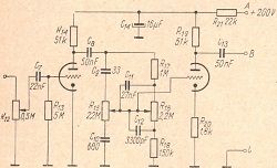
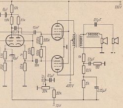
Figure 9 shows a schematic diagram of the amplifier. As you can see, the number of tubes and elements has been significantly reduced to a minimum. One of the ECC83 electron tube triodes works in the first stage. The anode of this vacuum tube is directly connected to the control grid of the next amplifier stage. This stage, equipped with the second triode of the ECC83 electron tube, works in a phase inverting system.
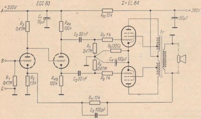
Fig. 9. Schematic diagram of the 10W amplifier
The phase reversal system used (the so-called "cathodine") is reliable in its simplicity. The output stage uses a pair of EL84 type tubes. Of course, in line with the requirements of modern Hi-Fi technology, this stage uses negative feedback in screen grids (the so-called "ultralinear system"). These grids are not connected - as is usually the case - directly to the high voltage source, but to special taps on the primary winding of the output transformer. The use of such feedback complicates the production of the output transformer somewhat, but it is very cost-effective as it reduces the nonlinear distortion caused by the power stage by about two times. In addition, the entire amplifier is subject to deep feedback, which runs from the secondary winding of the output transformer to the cathode of the pre-amplifier (the left triode system in the diagram). The implementation of the feedback covering the entire amplifier is possible, among others, thanks to the direct coupling of its first two stages.
The following parts and components are needed to make the amplifier:
All About Electric Guitar - Part I.
- Details
- Category: Radioamator i Krótkofalowiec
- Hits: 5158
Eng. Konrad Widelski
All About Electric Guitar - Part I
Radioamator i Krótkofalowiec Polski, Year 17, September 1966, No. 9
Due to the unflagging interest in electric musical instruments, and especially in such a very popular electric guitar - we are publishing the first part of an article written on this subject. The entire study, consisting of three parts, should give interested persons an answer to their doubts.
An electric guitar differs from a normal (mechanical) guitar in that it requires a suitable amplification device for its use. However, before we take a closer look at this apparatus, we will devote some space to the guitar itself. Its principle of operation is by no means complicated. Figure 1 shows a schematic diagram of the so-called magnetoelectric transducer, which is an essential element of the instrument.
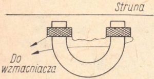
Fig. 1. Construction of a magnetoelectric transducer
Such a transducer consists of a permanent magnet and two spools with a winding made of thin insulated wire, mounted near its poles. The whole thing is placed directly under the steel strings of the instrument. During play, the string set in motion changes its distance from the front part of the magnet. This, in turn, causes changes in the magnetic flux in the system and the induction of electromotive forces in the winding. The electrical voltages produced by the transducer most closely correspond to the vibrations of the string, and thus to the sounds it produces. These voltages should then be suitably amplified and reproduced through the loudspeaker.
The mechanical vibrations of the air generated by the loudspeakers perceive listeners as sound impressions. A block diagram of this type of electroacoustic set is shown in Figure 2.
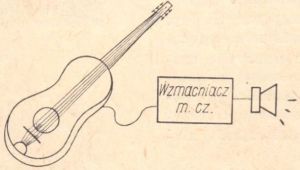
Fig. 2. Block diagram of the electroacoustic set
You can also use an existing standard mechanical guitar as an electric guitar. For this purpose, a magnetoelectric transducer should be mounted to it. Such transducers are factory-produced and sold in music stores for about PLN 100.
The transducer/pickup can be easily attached to your guitar, following the instructions given in the pickup's factory manual.
Making the transducer yourself, although it is also possible, should probably not be an option, because it is a task (especially in relation to the mechanical part) that is too difficult to do at home.
Stereo on a Shoestring
- Details
- Category: Electronics Illustrated
- Hits: 6423

Ernest Wayland
Stereo on a Shoestring
Electronics Illustrated 1958/10
The most exciting news for the hi-fi music listener since the introduction of the LP record is the development of the stereo disc. Stereo records now available take you from the blaring brass band of the bullfight ring to the whirling three-quarter time of the Strauss walts... and the stereo bandwagon is just beginning to roll/ By the time you read this, the record bins will be chock full of music for every taste - the designed for "two-ear" listening.
The big question is - How much? What do the stereo records and a playback machine costs? The good news is that you don't need the wealth of Midas to set yourself up with three dimensinal hi-fi. The present list price of the stereophonic records averages only about a dollar higher than a standard LP.
How about the playback equipment? Go about it the right way, and you can match the stereo records in cost, with a complete setup for approximately fifteen dollars.

The two stereo channels are fed separately to each of the hearing aid type headphones. The two knobs seen at lower left are optional volume controls

Modern High-End Valve Amplifiers based on toroidal output transformers
- Details
- Category: Books
- Hits: 5314

Ir. Menno van der Veen
Modern High-End Valve Amplifiers based on toroidal output transformers
Elector Electronics, Dolchestr, England, 1999
CONTENTS
- About the author (xiii)
- Introduction (xv)
- Why Valve Amplifiers?
- Output Teansformer Specifications
- The Output Transformer, Valves and Loudspeaker
- The Output Transformer in the Complex Domain
- Frequency-Domain Calculations for Toroidal Output Transformers
- Theory of Overall Negative Feedback
- Output Transformer Low-Frequency Tuning
- Special Output Coupling Techniques
- Single-ended Toroidal Output Transformers
- Building a Push-Pull Valve Amplifier: the Phase Splitter
- Building a Push-Pull Valve Amplifier: from 10 to 100 Watts
Read more: Modern High-End Valve Amplifiers based on toroidal output transformers
Build your own audio valve amplifiers
- Details
- Category: Books
- Hits: 11810

Rainer zur Linde,
Build your own audio valve amplifiers
Circuits for hi-fi and musical instruments
Elector Electronics (Publishing) P.O. Box 1414 Dorchester England DT2 8YH,
First Published in the United Kingdom 1995, This Edition September, 1997
Contents
Introduction
To most people working in electronics, the thermionic valve or electron tube is history. Indeed, few of us would be content nowadays without the ease of use, the technical quality, the low weight and the small dimensions of transistorized or integrated electronic equipment. None the less, for many hi-fi enthusiasts and musicians, a valve amplifier still forms the nucleus of their audio equipment. The combination of modern high-quality peripheral equipment (signal sources, loudspeakers) and a classical valve amplifier to come into their own as far as tonal quality is concerned. In modern hi-fi valve amplifiers much attention is paid to obtaining a signal transfer that is as nearly linear as possible. This obviates the need of complex tone control, which is the past were necessary to mask the deficiencies of signal sources then available. For instance, a CD player does not produce stylus noise which, when the audio was young, was combatted by chopping off the higher frequencies so as to obtain an acceptable sound quality (which modern listeners would not tolerate).
Whether it is nostalgia, interest in the technical parameters, the appeal of a gleaming amplifier chassis with softly glowing valves, respect for the technical know-how of earlier generation, or perhaps the firm conviction that the sound of a valve amplifier can not be bettered, it is a fact that this technical tradition, which deserves a place of honour in any science museum, is still in demand. It is particularly gratifying that many of the younger generation admire valve amplifiers. Perhaps this is due to the popularity of the electric guitar.
The field of the thermionic valve is extensive, shown by the enormous amount of literature it attracted in the 1960s.
This book is intended for a broad cross-secion of the public: apart from projects for preamplifiers, power amplifiers, and two amplifiers for musical instruments, aimed at the practical audio/hi-fi enthusiast, it offers much information on the operation od electron tubes, while the first chapter gives a short history of the thermionic valve.
- Part 1. GENERAL
- Chapter 1 - History of the thermionic valve (1)

- Chapter 2 - Operation of the electron tube (39)
- Chapter 1 - History of the thermionic valve (1)
Marantz 40/20-watt Power Amplifier - Marantz Audio Consolette
- Details
- Category: Audio USA
- Hits: 6241
Marantz 40/20-watt Power Amplifier - Marantz Audio Consolette
(Equipment Report)
AUDIO, AUGUST, 1956, VOL. 40, No. 8 (Successor to RADIO, Est. 1917).
If the average audiofan were to start building a preamplifier-control unit exactly fo suit his fondest dreams as to performance, absence of hum and noise, flexibility of control, and over-all appearance, it is quite likely that he would come quite close to dublicating the Marantz Audio Consolette - if he had the necessary ezperience, ability, and perseverance. And that is just about what Saul Marantz did, and over many months he worked out the design. The rezult was sufficiently "commercial" to warrant putting the unit on the marked. The performance curves in Fig. 1 show why.
Read more: Marantz 40/20-watt Power Amplifier - Marantz Audio Consolette
Hi-Fi 20W amplifier with psophometric volume control
- Details
- Category: Radioamator i Krótkofalowiec
- Hits: 5129
Hi-Fi 20W amplifier with psophometric volume control
Author: Stanisław Głowacki
Radioamator i Krótkofalowiec, Year 15, December 1965r., No 12
The human ear is not equally sensitive over the entire range of audible frequencies. It shows maximum sensitivity for frequencies ranging from about 1kHz to 3kHz, and this property occurs the stronger, the weaker the intensity of the sound perceived by the ear. This non-linear frequency response of the ear reduces the perceived sound experience when listening to music at low volume levels. At high sound levels the differences in ear sensitivity decrease and the reception is more accurate. It follows from the above that the adjustment of the volume of the reproduced broadcasts should be related to the adjustment of the frequency characteristics of the loudspeaker amplifier.
At a low volume level, i.e. with lower amplification of the amplifier, the low tones and high tones should be emphasized in relation to the medium tones, or the medium tones from 1 ÷ 3kHz should be muffled in relation to the low and high tones, and so much more, the smaller it is. power output from the amplifier. As a result, it is possible to achieve such changes in the characteristics of the amplifier that the ear will perceive the emission with the full balance of sounds, regardless of the output power.
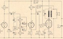
Fig. 1 shows a schematic of a high-quality amplifier that meets the above conditions. The 20W output power allows you to amplify large rooms or drive a large sound column.
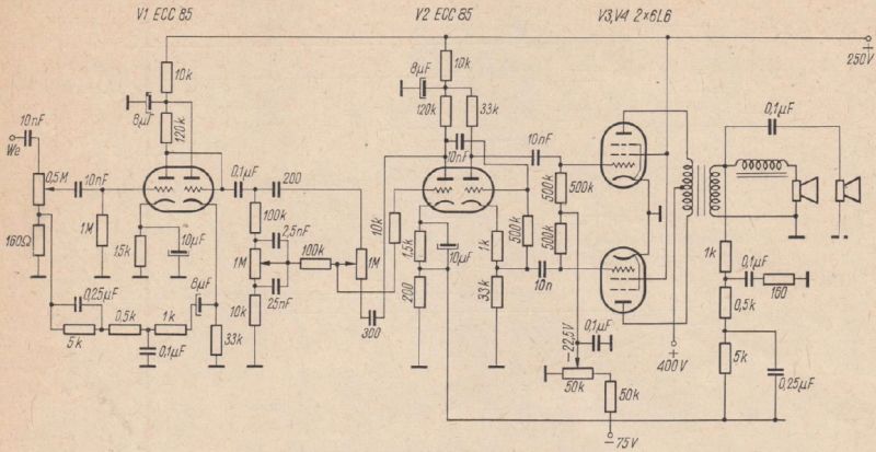
Fig. 1. Schematic diagram of the 20W power amplifier
The first stage of the amplifier with the ECC85 electron tube is a voltage amplifier with a cathode follower that controls the low-resistance quadruple of the negative feedback circuit. The frequency response of the quadruple has a flat maximum in the range of 1 to 5kHz, so that the negative feedback at these frequencies is the strongest. The reverse voltage Uzw is fed to the opposite end of the volume control potentiometer in relation to the voltage Uo controlling the amplifier. The feedback voltage is deposited on the resistance of the potentiometer and the internal resistance Ro of the signal source Uo, as shown in Fig. 2.
Read more: Hi-Fi 20W amplifier with psophometric volume control
How to make a push-pull transformer for a low frequency amplifier
- Details
- Category: Radioamator i Krótkofalowiec
- Hits: 5388
![]()
How to make a push-pull transformer for a low frequency amplifier
Author: Ryszard Zarzecki
Radioamator i Krótkofalowiec, Rok 19, Sierpień 1969r., Nr 8
(Radio amateur, Year 19, August 1969, No. 8)
When designing push-pull amplifiers, it is often difficult to acquire or manufacture a suitable output transformer. The Soviet monthly "Radio" no. 2/1967 presents a simple method of making such a transformer. For this purpose, two identical, "normal" output transformers are needed (for example from a "Pionier" type receiver). Metal clamps and a package of simple plates closing the core should be removed from these transformers, and plates of the "E" type should be left together with the bodies with windings placed on them.
Transformer cores with windings should be put together as shown in Fig. 1.
![]()
Fig. 1.
In this way, the assembled transformers are connected and squeezed with a new metal clamp, and then - the beginning of the anode winding of one transformer is connected to the end of the anode winding of the other transformer (Fig. 2).
Read more: How to make a push-pull transformer for a low frequency amplifier
Page 2 of 10
Select your language
")
")
")
")
")