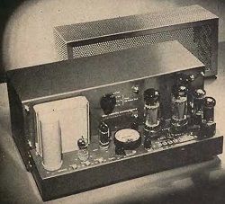
Marantz 40/20-watt Power Amplifier - Marantz Audio Consolette
(Equipment Report)
AUDIO, AUGUST, 1956, VOL. 40, No. 8 (Successor to RADIO, Est. 1917).
If the average audiofan were to start building a preamplifier-control unit exactly fo suit his fondest dreams as to performance, absence of hum and noise, flexibility of control, and over-all appearance, it is quite likely that he would come quite close to dublicating the Marantz Audio Consolette - if he had the necessary ezperience, ability, and perseverance. And that is just about what Saul Marantz did, and over many months he worked out the design. The rezult was sufficiently "commercial" to warrant putting the unit on the marked. The performance curves in Fig. 1 show why.
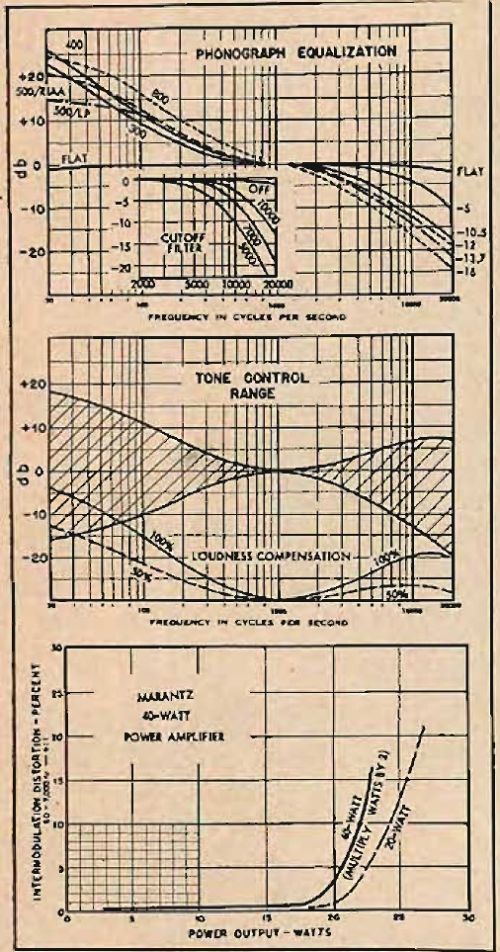
Fig. 1. Performance curves for the Marantz amplifier and Audio Consolette.
And with a successful Audio Consolette on the market, it was only logical that a power amplifier of equivalent performance should be developed to round up the line. The amplifier is shown in Fig. 2 and the Consolette in Fig 3.
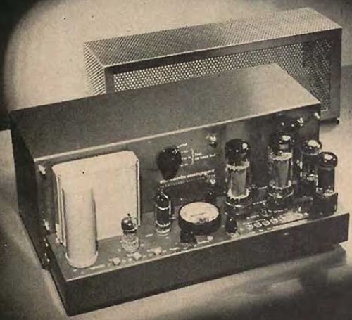
Fig. 2. The 40-watt power amplifier with the perforated grille cover removed to show the meter and test switch as well as the adjustable controls.

Fig 2a. Schematic of the Power Amplifier. The switch in the plate circuit of the output stage adjusts for maximum outputs of 40 or 20 watts, yet without changing gain.
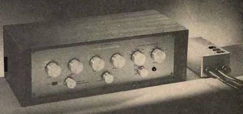
Fig. 3. The Audio Consolette in its wood housing.
The amplifier has several unique features. In the first place, it may be used as a 20-watt triode amplifier or as a 40-watt Ultra-Linear unit, the choice being made simply by throwing a switch. The output tubes are 6CA7/EL34, working at a plate voltage of 465 and with fixed bias. An illuminated meter on the chassis permits correct adjustment of bias, d.c. balance of the plate currents in the output stage, and a.c. balance of the entire amplifier. A switch on the panel above the meter has four positions - NORMAL, BIAS, D.C. BAL. and A.C. BAL. Separate controls are provided for adjustment of each of the three parameters. To prevent leaving the switch in any of the test positions the output is shorted except in the NORMAL position.
The input to the amplifier is unusual in that there is a built-in high-pass filter that serves to eliminate practicaly anything below about 10 cps, thus reducing the damaging effect of low-frequency signals which are sometimes present because of faulty record player or pickup arm - or even in the records themselves, such as once-perprevolution bumps which can ruin reproduction (to say nothing of the loudspeaker) when followed by a high-powered amplifier. Additional jacks provide for a lower level input (6 db) and for eliminating the filter where it is not needed. The filter will not affect the audible frequency response of the amplifier, however, even if left in at all times.
The gain of the amplifier is practically unchanged when switched from 20-watt condition to the 40-watt mode. In the PREAMP input, a 1-watt output is obtained from an input of 0,3 volts for 40 watts and 0.315 volts in the 20-watt position. The other two jacks have the same input-voltage requirements for a 1000-cps signal - 0.104 volts for the high-power setting, and 0.109 for the low-power setting. Measured hum output was .0004 volts across 16 ohms which is 80 dB below 1 watt, or 96 dB below maximum output as usually stated in specifications.
In the 40-watt setting, IM distortion is below 1 per cent up to 35 watts, just barely over 2 per cent at 40 watts; at the 20-watt setting, the distortion remains below 1 per cent at 19 watts, reaching 2 per cent at 21 watts. Distortion is below 0.2 per cent at one tenth the rated output.
A wide variation in damping is available - there are three separate returns for the variable-damping action, together with a control which adjusts the damping to suit the requirements. Listening tests show a minimum of effect with high-quality speaker; with those not properly housed or with resonant peaks, the variable-damping feature assumes greater importance.
The Audio Consolette
As would be expected, the preamplifier cirves in the Consolette are among the most we have encountered. Tone controls provide relatively conventional response, but the loudness compensator is unique in that it is continuously variable yet separate from the volume control. The curves in the center section of Fig. 1 show the response at 50 per cent rotation and at full on, with any intermediate degree being available. The cutoff filter has four positions - FLAT, 10 KC, 7 KC, and 5 KC - with the curves shown in the insert in the upper section of Fig. 1. The schematic of Fig. 4 omits the input switching to save space, but there are three low-level inputs (microphone, low-level phono, and medium-level phono), and four high-level inputs (tuner, TV, extra, and tape). The tape input is controlled by a slide switch which connects the output of the tape recorder to the high-level input so that it may be used to monitor while making recordings on a three-head machine, as well as for playbacks from the more common two-head machines. The selector switch thus controls the feed to the tape recorder at all times, and also to the remainder of the amplifier when the slide switch is in the right position (in the insert of Fig. 4) for monitoring what is being fed to the recorder, while if the switch is in the lefr position the remainder of the amplifier is connected to the tape recorder output for monitoring off the tape.
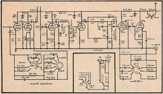
Fig. 4. Schematic of the Audio Consolette, with input switching eliminated to reduce the size. The insert shows the switching for tape recorder feed and monitor output.
The Consolette is powered by a separate supply, shown at the right in Fig. 3, which furnishes 320 volts for the plate circuits and 18.9 volts for the three heaters in a series-parallel arrengement, as well as for the pilot light. Both supplies are heavily filtered, the high voltage with 200 μF of capacitance and the heater supply with 1300 μF. With the volume control in the maximum position, the hum (and noise) in the output is less than 0.1 millivolts. In the microphone and phono positions, hum is less than 0.5 mv at normal settings of the volume control, or more than 66 dB below 1 volt output.
The phono preamplifier is equipped with two separate controla - one for the bass and one for the treble. When using mictophone, both controls are normally set at FLAT. Any desired combination of low- and high-frequency equalization may be used, providing all the flexibility that should ever be required. The dual volume control prevents overloading of the first stage of the tone-control stages, while reducing hum and noise in the intermediate stages by the section just preceding the cathode-follower output stage.
Signal levels required to produce a 1-volt output are as follows: tuner, TV, extra, and tape, .056 volts; microphone and low-level phono, 1.25 milivolts; medium-level phono, 2.3 mV. The signal supplied to the tape recorder is the same as that of the high-level input sources, and it is 45 times the input from the phono pickup or microphone.
From these performance curves and data, it is seen that the Audio Cobsolette and the Power Amplifier are both of exceptionally high quality, which is carried out in the appearance of the units from the outside. Internally, they show every evidence of careful design and workmanship. The wiring is neat and efficient, cabled where possible. Parts placement is such as to minimize the length of connecting leads, and high-quality parts are used throughout, one example being in the choice of Ohmite (Allen Bradley) variable controls in every instance. Deposoted carbon resistors are used in every plate-load position and for unbypassed cathode resistors. Critical values of both capacitors and resistors are maintained by the use of 2 per cent tolerance components. Both of these units may truly be called "deluxe".
The content of the article for electron tube enthusiasts was provided by Grzegorz Makarewicz 'gsmok'


