Eng. Konrad Widelski
All About Electric Guitar - Part I
Radioamator i Krótkofalowiec Polski, Year 17, September 1966, No. 9
Due to the unflagging interest in electric musical instruments, and especially in such a very popular electric guitar - we are publishing the first part of an article written on this subject. The entire study, consisting of three parts, should give interested persons an answer to their doubts.
An electric guitar differs from a normal (mechanical) guitar in that it requires a suitable amplification device for its use. However, before we take a closer look at this apparatus, we will devote some space to the guitar itself. Its principle of operation is by no means complicated. Figure 1 shows a schematic diagram of the so-called magnetoelectric transducer, which is an essential element of the instrument.
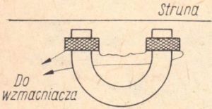
Fig. 1. Construction of a magnetoelectric transducer
Such a transducer consists of a permanent magnet and two spools with a winding made of thin insulated wire, mounted near its poles. The whole thing is placed directly under the steel strings of the instrument. During play, the string set in motion changes its distance from the front part of the magnet. This, in turn, causes changes in the magnetic flux in the system and the induction of electromotive forces in the winding. The electrical voltages produced by the transducer most closely correspond to the vibrations of the string, and thus to the sounds it produces. These voltages should then be suitably amplified and reproduced through the loudspeaker.
The mechanical vibrations of the air generated by the loudspeakers perceive listeners as sound impressions. A block diagram of this type of electroacoustic set is shown in Figure 2.
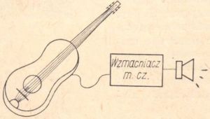
Fig. 2. Block diagram of the electroacoustic set
You can also use an existing standard mechanical guitar as an electric guitar. For this purpose, a magnetoelectric transducer should be mounted to it. Such transducers are factory-produced and sold in music stores for about PLN 100.
The transducer/pickup can be easily attached to your guitar, following the instructions given in the pickup's factory manual.
Making the transducer yourself, although it is also possible, should probably not be an option, because it is a task (especially in relation to the mechanical part) that is too difficult to do at home.
OPERATION OF AN ELECTRIC GUITAR WITH A RADIO
A necessary complement to the electric instrument is an electronic amplifier with a loudspeaker. It is an extensive and complex issue, because amplification equipment is complicated and quite expensive. However, it is worth remembering that the final effect, i.e. the sound of the instrument, is determined by the amplifying equipment, not the guitar as such. The guitar - or more precisely its transducer/pickup - delivers signals of more or less similar quality in each case. Elements such as the shape, color or price of the guitar do not have a greater impact on this quality. Only the electronic amplifier (and the loudspeaker) converts these signals into acoustic effects, the quality of which - depending on the capabilities of this apparatus - can be significantly differentiated. In this area there is - as it is easy to guess - a fairly close relationship between the quality and cost of the apparatus.
A cheap electro-acoustic set, consisting of a small amplifier and loudspeaker, gives completely average acoustic effects. On the other hand, during stage performances, we hear the effects of very complex equipment, the costs of which reach at least tens of thousands of Polish zlotys, and in the case of an ensemble of instruments, they are even greater.
For an amateur, there are two main options. The simplest and cheapest is to use your radio. The second option is the independent construction of the amplifier. This is not a difficult task for a radio amateur with some practice in this area, but less advanced people should use the appropriate detailed construction description. We advise readers without any amateur radio preparation to use a radio receiver to work with the guitar.
The "gramophone" input of an average radio receiver, which we use to work with an electric guitar, is not very sensitive. It is sufficient for cooperation with a turntable, while in the case of cooperation with a guitar, the sounds will probably be too weak. Then you should use a simple additional transistor amplifier, which is quite easy to make yourself.
Figure 3 shows a schematic diagram of such a preamplifier.
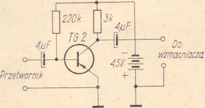
Fig. 3. Schematic diagram of the preamplifier
And here is a list of elements needed for its construction (some of them have values given in the range "from ... to", i.e. you can use an element of any value within these limits, for example the list includes an electrolytic capacitor 2 ÷ 10μF / 3 ÷ 12V, while the diagrams show capacitors with 4μF values):
- transistor (any type) 1 pc.
- electrolytic capacitor 2 ÷ 10μF / 3 ÷ 12V 2 pcs.
- resistor 3 ÷ 10kΩ / 0.1 ÷ 0.5W 1 pc.
- resistor 100 ÷ 500kΩ / 0.1 ÷ 0.5W 1 pc.
- "flat" battery 4.5V 1 pc.
For amateurs with little practice, we advise you to initially assemble the system provisionally, as shown in Fig. 4. This will allow you to check both your own skills and the quality of the parts and components used.
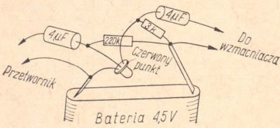
Fig. 4. Assembly diagram of the preamplifier
A properly assembled preamplifier should work properly right away. It may only be necessary to select (if the preamplifier introduces noticeable distortions) the value of the resistor polarizing the base of the transistor - within the limits given in the parts list. After obtaining correct results, the preamplifier should be disassembled and assembled again, this time permanently. The arrangement of the preamplifier's elements can be completely arbitrary, and the preamplifier itself is most conveniently placed with the power supply inside the guitar's box.
The current drawn from the battery is so small that even without switching it off it lasts for several months. After this period, regardless of whether the preamplifier has been used or not, the battery should be replaced with a new one.
ECONOMIC ASPECTS
Currently, we will consider the issue of the electric guitar from the point of view of economic aspects, giving only final conclusions.
- Whoever has an ordinary (mechanical) guitar should limit himself to modernizing it by adding the factory pickup. Your radio should be compatible with such a guitar. Building an amplifier yourself, even a completely simple one, is neither easy nor profitable. Buying an expensive factory-made amplifier would be all the more unjustified.
- Those who have some practical preparation in the field of radio engineering and have elements that can be used, such as transformers, loudspeakers, potentiometers or other components, can build an amplifier even to work with an ordinary, "converted" guitar.
- When working with a radio receiver, the guitar does not give any extraordinary effects - only that it works at all. The owner of a good factory electric guitar should expect more from it, and this can only be achieved with the right amp. For such a guitar it is definitely worth building an amplifier whose component parts cost about several hundred zlotys. If the guitar is not only a temporary "hobby", you can also think about buying a factory amplifier, although it is quite expensive (eg LUNA amplifier - price around 3500 PLN).
- Whoever is just thinking about owning an electric guitar should not buy an ordinary guitar to convert it into an electric one, although it is the cheapest solution. Converting a regular guitar to an electric one should be of interest only to those who already have such a guitar. To sum up (guitar and pickup) it is quite a significant expense, and as a result you get only a "substitute" for an electric guitar. After the first emotions, it will no longer satisfy us. Whoever thinks about the guitar seriously, should buy a "real" electric guitar, even though it is quite a significant expense (over PLN 3,000).
SIMPLE GUITAR AMPLIFIER
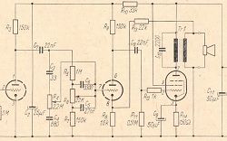
Building an amplifier on your own - even the simplest one - is not easy, but given the great interest, we present a description of such a circuit, its schematic diagram (Fig. 5) and a list of components. It is based on easily achievable elements, so completing the parts should not be a problem.
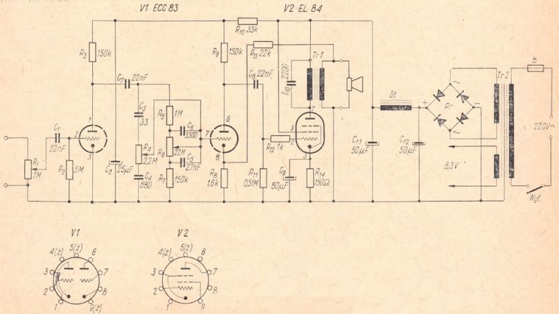
Fig. 5. Schematic diagram of a simple low-frequency amplifier
LIST OF COMPONENTS
Resistors
- R1 - logarithmic potentiometer 0,5÷1,0MΩ
- R2 - 3÷6MΩ/0,1÷0,5W
- R3, R9 - 100÷200kΩ/0,25÷0,5W
- R4, R6 - linear potentiometer 2,2MΩ
- R5 - 1MΩ/0,1÷0,5W
- R7 - 150kΩ/0,1÷0,5W
- R8 - 1,2÷2kΩ/0,1÷0,5W
- R10 - 22÷51kΩ/0,25÷0,5W
- R11 - 0,47÷0,68MΩ/0,1÷0,5W
- R12 - 0,51÷1,5kΩ/0,1÷0,5W
- R13 - 10÷51kΩ/0,1÷0,5W
- R14 - 140÷160Ω/1÷2W
Capacitors
- C1, C7, C8 - styroflex 22÷50nF/250÷500V
- C2 - electrolytic 20÷50μF/375÷500V
- C3 - ceramic 33pF
- C4 - ceramic 680pF
- C5 - styroflex 27nF/250÷500V
- C6 - styroflex 3300pF/250÷500V
- C9 - electrolytic 20÷50μF/8÷30V
- C10 - ceramic 2200pF
- C11, C12 - electrolytic 2×20÷50μF/375÷500V
Electron tubes
- V1 - ECC83
- V2 - EL84
Transformers
- Tr1 - output/loudspeaker (see text)
- Tr2 - mains (see text)
Other items
- Dł - filter choke, any type (see text)
- Pr - rectifier SPS-6B-250-85 (or similar)
- W - mains switch (any type)
In addition, you need mounting elements such as electron tube sockets, sockets, a fuse, a power cord, a chassis, etc.
The power transformer can be a transformer from any domestic receiver with an EL84 type loudspeaker electron tube ('Tatry', "Bolero", "Karioka", "Rumba", "Sonata" etc.). Anyone who has the appropriate materials can make this transformer on their own, guided by the following data:
- core diameter: approx. 8cm2
- primary winding: 1150 turns of wire Ø0.30 ÷ 0.35mm
- secondary winding: 1330 turns of wire Ø0.20 ÷ 0.25mm
- filament winding; 38 turns of wire Ø0.7 ÷ 1.0mm
As a loudspeaker (output) transformer, a factory transformer from any domestic receiver with an EL84 type loudspeaker electron tube can be used. Who would like to make this transformer on their own should be guided by the following data:
- core diameter: approx. 4cm2
- primary winding: approximately 3000 turns of wire Ø0,16÷0,25mm
- secondary winding: approximately 75 turns of wire Ø0.6 ÷ 1.0mm
Any choke made of wire not thinner than 0.15mm can be used as a choke. It can be a choke from any type of receiver or TV, as well as any mains or loudspeaker transformer.
Approximate data for making the choke yourself:
- core cross-section: about 2÷4cm2
- winding: about 1000 ÷ 3000 turns of the wire with a diameter of Ø0.15 ÷ 0.25mm.
Construction and assembly of the amplifier
The following description of the amplifier assembly is intended for less advanced radio amateurs. This description covers the essential steps that must be performed in a relatively detailed manner. We pay attention to the sequence of works performed; this is one of the best ways to get the right results. By following the steps described and checking the assembled piece of apparatus immediately, you will avoid many unpleasant surprises. Only really advanced radio amateurs can afford a different way of assembling the whole thing, for whom finding a fault or a faulty element on their own is not a problem.
The construction of the amplifier should be started with the base of the aluminum or galvanized iron sheet, about 0.5 mm thick. An example of the arrangement of the main parts is shown in Figure 6. We start the assembly of the system "from the end", that is, from the power supply, and perform it gradually, immediately checking the operation of the part of the system made.
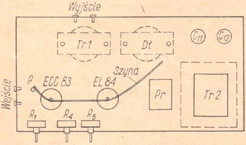
Fig. 6. An example of the arrangement of the main elements of the amplifier (view from the bottom of the chassis)
In the event that the correct results of this check are not obtained, it is absolutely necessary to proceed with the assembly no further. A radio amateur who does not have adequate experience is completely helpless before assembling an amplifier that "does not want to play" - and simply does not know what to do. Most often it ends with dismantling the amplifier.
So we assemble the amplifier according to the following plan:
- Make a metal base (chassis) and mechanically mount the basic elements of the apparatus, such as: electron tube sockets, mains and loudspeaker transformers, potentiometers, sockets, switches, etc. Use screws with nuts everywhere. Install the mains cord, assemble the primary circuit of the mains transformer with the mains switch. End the cord with the mains plug.
- Assemble the heating circuit of V1 and V2 tubes from two twisted rather thick wires in plastic mattings. These cables are led along the base plate from the appropriate terminals of the mains transformer to pins 4 and 5 of the V2 electron tube, and then to the V1 electron tube. In the electron tube's base, one of the heating wires is connected to the shortened legs 4 and 5, while the other - to the foot 9.
- Check the work done so far. Connect the power cord to the power socket. Before switching the system on, make sure that the previously unused, loose wires of the mains transformer do not touch anything. Switch on the system with the power switch. Put the ECC83 and EL84 electron tubes in the right place in the electron tube sockets. Filaments of filaments of electron tubes and cathodes should glow soon, which is easy to observe from the outside (viewed from the top or bottom of the electron tube). Leave the system on for a few minutes and then switch it off. Remove the cord from the socket and remove the electron tubes from their sockets.
- Assemble the power supply, i.e. fasten the rectifier with screws (directly on the metal base to dissipate heat), the choke and the electrolytic capacitors. Connect the rectifier in accordance with the marking on its housing: connect the terminals of the transformer secondary winding to the small "hoses" denoting alternating voltage, the contacts marked "+" with the "plus" of the electrolytic capacitor, and the contacts marked "-" with its "minus". Fasten the electrolytic capacitors using insulating washers (Fig. 7) so that their casing does not touch the base directly. Make the remaining connection in accordance with the schematic diagram, i.e. connect the choke ends to the capacitors.
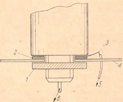
Fig. 7. Installation of the electrolytic capacitor:
1 - capacitor nut, 2 - insulating washer, 3 - contact washer, 4 - chassis, 5 - to the ground rail, 6 - to the "+" rectifier
- Test the power supply operation, temporarily switching on two 220V/15W bulbs connected in series to the power supply (meaning to the poles of the electrolytic capacitor C11). After the system is connected to the mains, the bulbs should glow visibly; otherwise, the correctness of previous manipulations should be checked.
- Perform the so-called the ground bus of the amplifier. It is a thick copper wire, about 1 ÷ 4 mm in diameter, connecting the central pins of both tube sockets. This wire (Fig. 6) is connected to the amplifier base at point P with a screw and a nut and a solder pad. The rail runs with its free end towards the electrolytic capacitors. The "minus" of the rectifier and the wires running from the electrolytic capacitor housing should be permanently connected to the rail made, this time permanently.
In addition, the pin 9 of the V1 (ECC83) electron tube, i.e. one of the glow circuit wires, must be connected to the rail. Without this connection, the amplifier cannot function properly (severe hum). - Install the elements belonging to the output stage (electron tube EL84) up to the mesh resistor R11 of the loudspeaker tube, inclusive. Solder the resistor and capacitor directly to the appropriate foot of the tube socket and to the grounding rail. The loudspeaker transformer is connected to the appropriate feet of the electron tube socket (according to the numbering in the diagram) with a mounting cable in plastic mattings, and the ends of its secondary winding with the output sockets of the amplifier. These sockets are provided with suitable insulating washers so that they do not come into contact with the metal base. We do not connect them yet with the earthing bar or the R13 resistor. We will make these connections only in the output stage of assembly, which will be mentioned later in the description.
- Check the operation of the output stage. To do this, put both electron tubes in their places, connect the amplifier to the mains and temporarily connect the output cables of the electric turntable to the ground bus and the control grid of the EL84 tube. While playing a record, a weak, but clear and clean broadcast should be heard from the loudspeaker. With the turntable disconnected, only a very faint, barely noticeable noise should be heard.
For these tests, any type of loudspeaker with a voice coil resistance of about 4 ÷ 15Ω can be used. The loudspeaker is connected to the amplifier's output sockets with a two-wire cable with banana plugs. If the amplifier does not work, check all connections made at this stage, or replace the EL84 tube. - Install the elements of the second gain stage (right ECC83 triode on the schematic diagram), i.e. the R10, R9, R8 resistor and the C8 and C2 capacitors. The triode grid is provisionally connected to ground through a 0.1 ÷ 1MΩ resistor. The elements connected in the schematic diagram with the ground of the system are, of course, connected to the earthing bar. All cables connecting elements of this stage should be short and run away from each other and other elements.
- Connect the amplifier to the mains and connect the electric turntable to the ground and control grid of the triode. A very loud and clear broadcast should be heard through the loudspeaker - without distortion. Do not remove the cord from the socket, but switch the amplifier off using the switch.
- Provisionally connect one output socket of the amplifier to ground (rail), and the other, through the R13 resistor, to the cathode of the triode already switched on to work. Turn on the amplifier while listening carefully. If, after the electron tumes warms up, you hear a rapidly increasing whistling or howl, turn the amplifier off immediately. These symptoms mean that our system was "aroused" as a result of incorrect connection of the feedback branches. This coupling is positive in this case.
In order to eliminate this phenomenon (whistle, howl), change the way of connecting the amplifier's output sockets: disconnect the earthed socket from the ground and connect it to the triode cathode through a resistor, and earth the other socket. After making this switch, we obtain a negative feedback and then the amplifier should not show any instability symptoms after being connected to the network. We then try to record a gramophone record again. The program should now be heard a bit quieter than during the previous rehearsal (without the negative feedback circuit connected), but definitely cleaner, softer.
It is possible to experimentally prove the beneficial effect of the connection made by the resistor of the output socket with the cathode of the triode, by listening to the plate fragments in both cases, i.e. with the negative feedback circuit on and off. If the results so far are satisfactory, the most difficult part of the work is already behind us. - Install all the remaining elements of the amplifier, i.e. the tone controls and the first gain stage. All connections in this part of the system should be made with the shortest possible cables. The wire going to the middle contact of the potentiometer (from the tube grid through the capacitor) can be additionally shielded or covered with a small plate connected to the ground of the system. Otherwise, a slight "hum" may occur, interfering with the normal operation of the amplifier.
Amplifier startup
The amplifier assembled strictly according to the above guidelines should work properly immediately after the assembly is completed. The first attempts are best to leave the input jacks free, with only the loudspeaker connected to the output jacks. After connecting the system to the network and warming up the tubes, a slight noise should be heard, disappearing after turning the volume control "to zero".
Then we check that the amplifier does not tend to oscillate. To this end, we turn "in all directions" the three knobs of the amplifier simultaneously: the volume control knob and two tone controls. Apart from the aforementioned slight hum, no sounds should be heard (whistling, growling, knocking, etc.). If such symptoms occur (which is possible, for example, with faulty, careless assembly), they can be eliminated either by increasing the value of the R10 resistor to about 50 ÷ 60kΩ, or by increasing the capacitance of the C2 electrolytic capacitor - even up to 100μF. If it turns out to be ineffective, you can try to use a resistor in the cathode circuit of the first gain stage (left triode of the ECC83 tube in the schematic diagram). Until now, this cathode was directly connected to the earthing bar. The resistor can have a value in the range of 500 ÷ 2000Ω. At the same time, the value of the mesh resistor of this tube can be reduced from 5MΩ to 1 ÷ 2MΩ..
The first tests with the amplifier are carried out using an electric turntable connected to the input sockets. We then check the operation of all regulators. The fact that the currently obtained volume of the broadcast is not much higher than the previous one is explained by the fact that the gain introduced by the first stage is almost entirely lost in the system of tone regulators, which introduce a significant attenuation of the signals.
A loudspeaker with a coil resistance of 4 ÷ 8Ω can work with the amplifier. For those who really care about good results, we recommend using a set of four GD18-13 / 2 speakers connected in series-parallel for the amplifier. The way of assembling and connecting the loudspeakers is shown in Figure 8.

Fig. 8. Set of 4 GD18-13 / 2 loudspeakers:
a - schematic diagram, b - connection ensuring the loudspeakers work in the right phase
Such a loudspeaker assembly has a resultant resistance of about 5Ω and a total power of about 8W. With the described amplifier, the output power of which is about 3 ÷ 4W, this set will work well, providing a good sound system even in a fairly large hall. The sensitivity of the amplifier is suitable for use with an average electric turntable. To work with an electric guitar, the sensitivity may be too low, so you should use a transistor preamplifier, which we have already mentioned.
After setting up the guitar-amplifier-speakers circuit, we make our first attempts - not without some emotion - The sensitivity of the amplifier can be pre-adjusted by selecting the value of the R13 resistor. With a smaller resistor, the sensitivity of the circuit decreases, with a larger one - it increases. The maximum sensitivity of the system occurs when the R13 resistor is completely disconnected (maximum resistance). The proper sensitivity of the amplifier is such that it is fully driven by a guitar (turntable) at the almost extreme maximum setting of the potentiometer regulating the volume of the program. If the sensitivity of the amplifier turns out to be too high, even with the R13 resistor value of about 10kΩ (lower values should not be used), it can be additionally reduced by connecting the first triode between the cathode and the mass of the resistor with a value between 500 ÷ 2000Ω (this cathode is connected in the diagram with mass directly).
In real conditions, the above-mentioned "full control" is difficult to determine, because we do not have equivalent measuring devices. Therefore, for full control, we can roughly assume the amplifier's tuning at which it operates at its maximum power, but without any noticeable ear distortions. Please note here that this is only true when loading the amplifier with a set of speakers with a total power exceeding that of the amplifier. In cases where the amplifier is loaded with a loudspeaker (loudspeaker set) with too low power, the distortions occur earlier, before the amplifier is fully driven.
(to be continued in the next issue)
The material was provided by Grzegorz Makarewicz, 'gsmok'


