
Radio engineering time travel (1926)
I invite you to look at the "pictures" related to radio technology. They come from various sources. The gallery has its sister version in Polish and Russian. Versions in other languages will be added successively. More detailed descriptions can be found in other language versions (articles are related and can be displayed by clicking on the icons with flags on the left, top of the TRIODA website). Of course, I will complement translations of signatures quite slowly. All descriptions are displayed using the present tense and not the past - this is not a mistake only deliberate action - a reference to the original descriptions from those years. In order not to delay the possibility of viewing the gallery, this site is made available as a "site under construction" - for which I apologize to all guests. At the beginning and end of each set of photographs there are links allowing to change the period - calendar year.
[Previous period] [Next period]
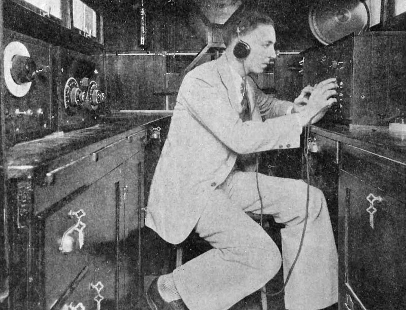
The Radio Detective - Compact Motorized Equipment Used by the 8th District Radio Inspector for Locating Interference.
Interior View of Car, Showing Arrangement of Testing Apparatus
(Radio for January, 1926)
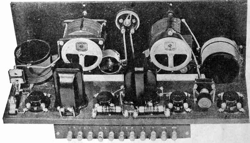
An Exceptional Four - Tube Receiver. A Modification of the LC Circuit Described in Oct. 1925 RADIO Employing Standard Coils and Adaptable to Batteryless Operation.
Rear View, Showing Baseboard Layout.
(Radio for January, 1926)
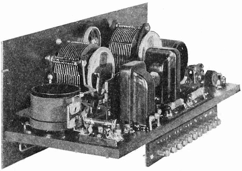
An Exceptional Four - Tube Receiver - End View of Completed Set.
(Radio for January, 1926)
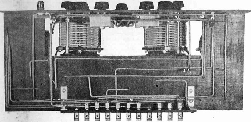
An Exceptional Four - Tube Receiver - Wiring Layout Under Baseboard.
(Radio for January, 1926)
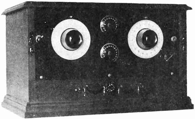
An Efficient One -Tube Set - The Second in the Series Started in December Radio
Panel View of One -Tube Regenerative Non-Radiating Receiver.
(Radio for January, 1926)

An Efficient One -Tube Set - Rear View of Receiver Showing Placement of Parts.
(Radio for January, 1926)
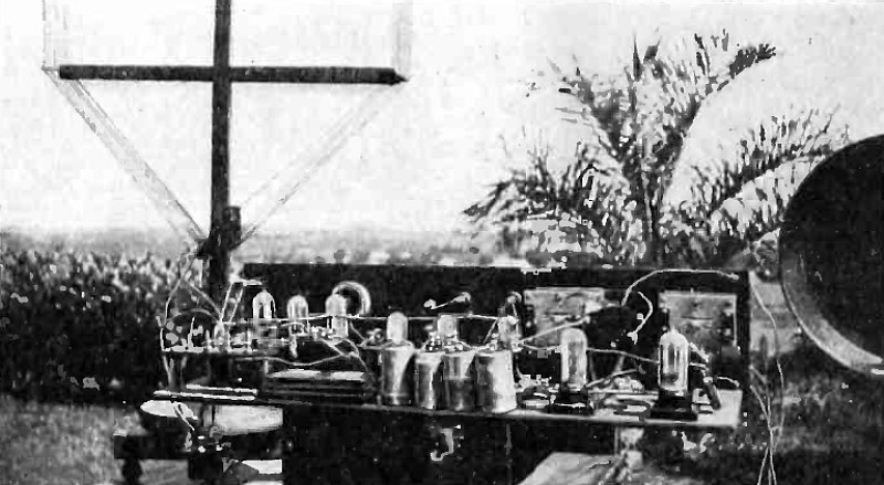
Radio In The Fiji Islands - A Graphic Account of Successful Radio Reception on a Far Away Isle.
Closeup of Set, Showing Mammoth "C" Batteries.
(Radio for January, 1926)
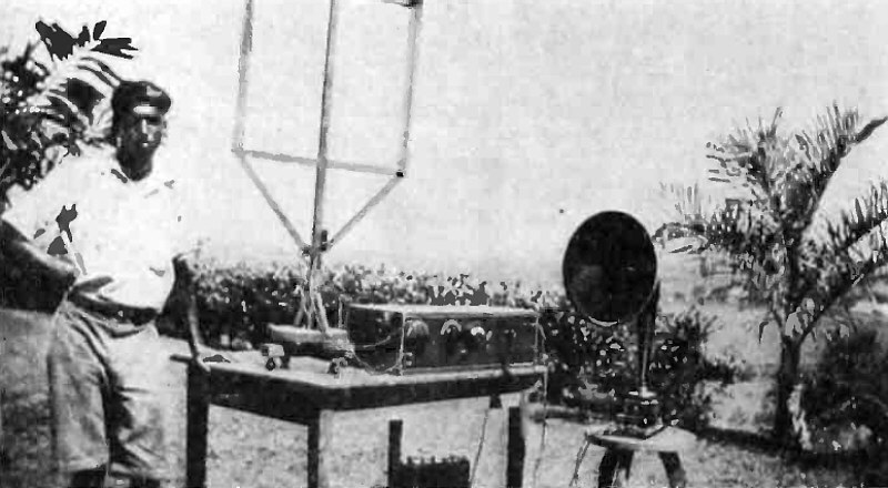
Radio In The Fiji Islands - .4 Best Superheterodyne at I.autoka, Fiji.
(Radio for January, 1926)
(Radio for January, 1926)
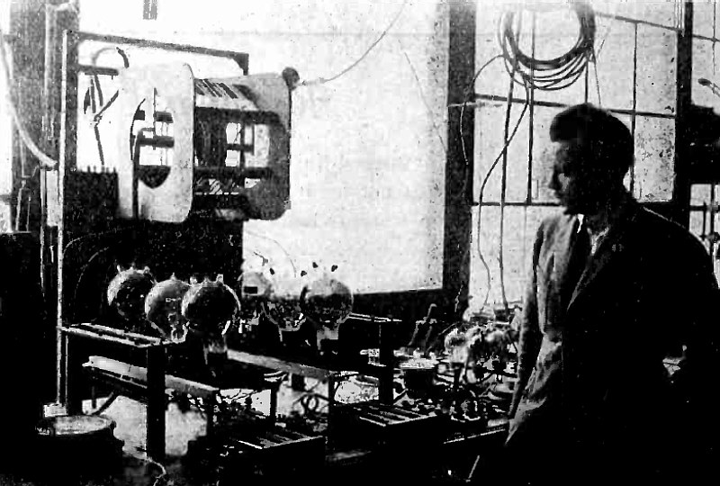
The Eiffel Tower Short -Wave Transmitter - A New and Novel Short Transmitter Developed by the French Signal Corps.
View of Transmitter, Showing Method of Mounting the Inductance Coils.
(Radio for February, 1926)
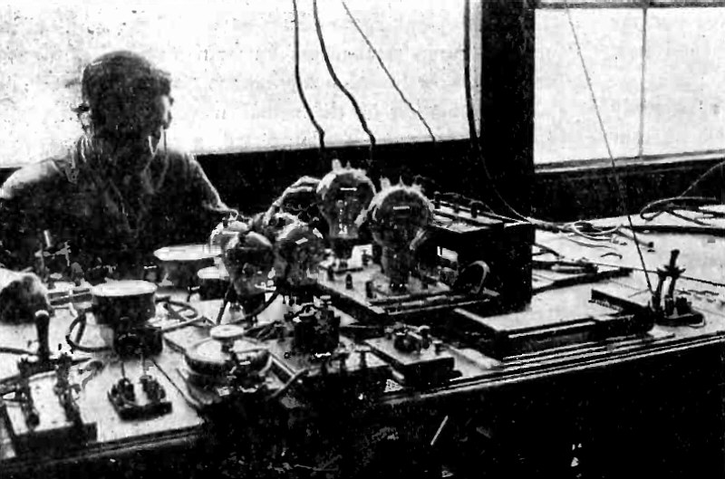
The Eiffel Tower Short -Wave Transmitter - A New and Novel Short Transmitter Developed by the French Signal Corps.
Grid Resistance Control Unit for Keying Transmitter.
(Radio for February, 1926)
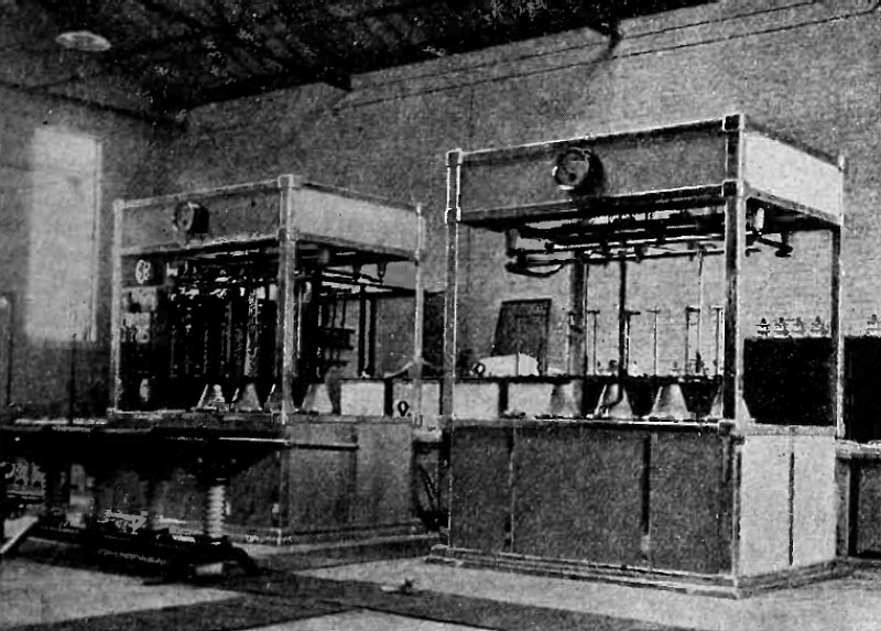
Broadcasting in The British Isles - Rectifier Panels at Daventry.
(Radio for February, 1926)
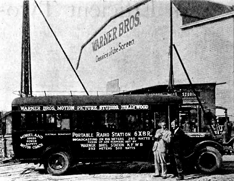
PORTABLE RADIO STATION 6XBR - Chas. Wellman, KFWB Announcer, and F. N. Murphy, Electrical Engineer Ready to Radiocast from 6XBR.
"6XBR is a 250-watt portable radiocast station operated on 108 meters in connection with KFWB at Hollywood, Calif., by Warner Bros. Moving Picture Studio. The apparatus is mounted on a motor coach 22 ft. long behind the dash, giving ample room. The antenna system consists of a 45-ft. and a 25-ft. collapsible tower which fold down on top of the truck, along which the counterpoise is also run. The transmitter is a coupled Hartley circuit with Heising modulation."
(Radio for February, 1926)
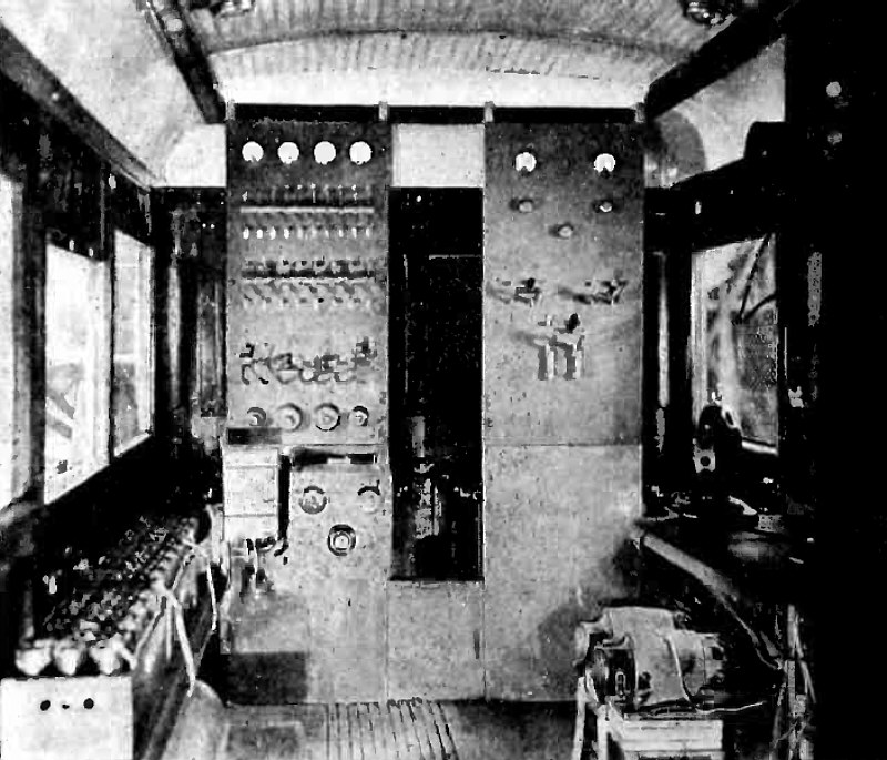
PORTABLE RADIO STATION 6XBR - - Interior View
(Radio for February, 1926)
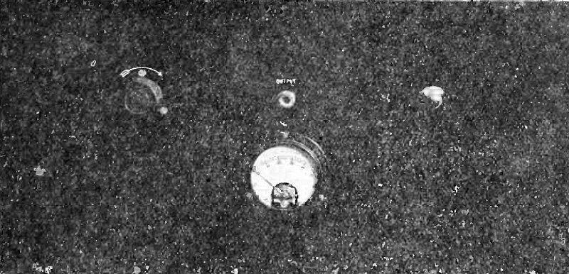
A High Quality Power Amplifier - Specific Directions for Building a Two-Stage Distortionless Audio Amplifier Giving Great Volume and Using A. C. Supply.
Panel View of High Quality Amplifier
(Radio for February, 1926)
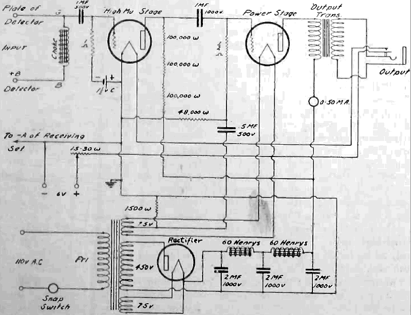
A High Quality Power Amplifier -Schematic Wiring Diagram.
(Radio for February, 1926)
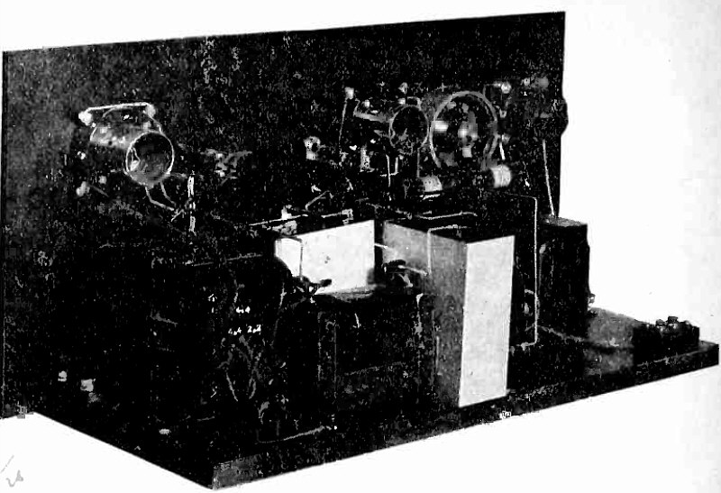
A High Quality Power Amplifier - Rear View, Showing Closeup of Apparatus.
(Radio for February, 1926)
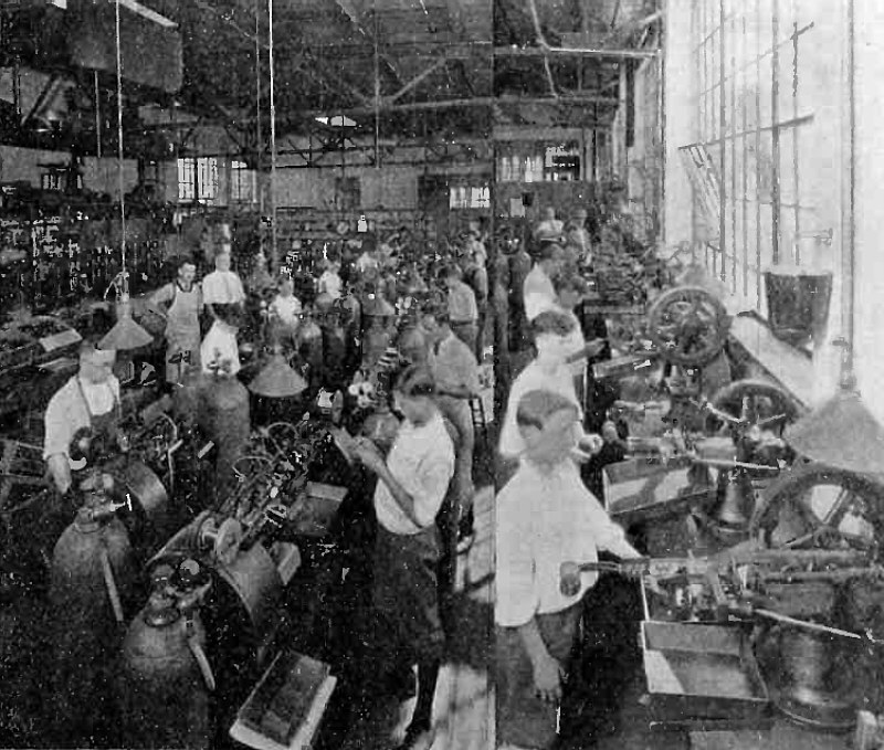
The Million-Dollar Bend. A Thrilling Story About the Battles Over the Evasion of Radio Tube Patents.
Wire Working Laboratory and Automatic Stamping Machines for Forming Metal Parts.
(Radio for February, 1926)
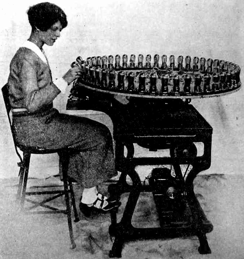
The Million-Dollar Bend. A Thrilling Story About the Battles Over the Evasion of Radio Tube Patents.
"Aging" Tubes by Means of a Tapered Filament Current Applied as Machine Revolves.
(Radio for February, 1926)
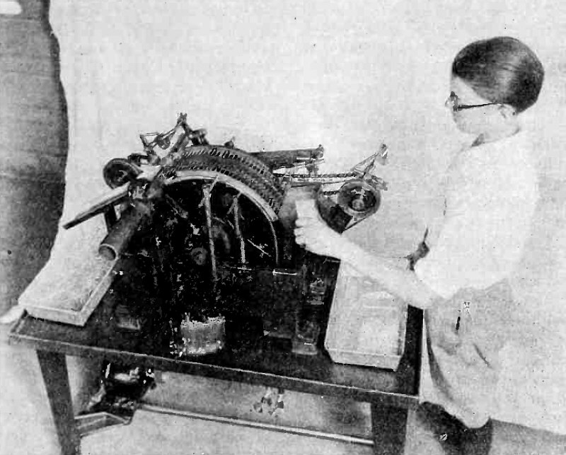
The Million-Dollar Bend. A Thrilling Story About the Battles Over the Evasion of Radio Tube Patents.
Crusher to Flatten Glass Stems and Seal in Seven Mounting Wires.
(Radio for February, 1926)
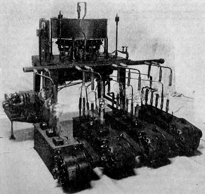
The Million-Dollar Bend. A Thrilling Story About the Battles Over the Evasion of Radio Tube Patents.
Latest Model of Automatic Radio-Tube Exhausting Machine, Showing Twelve Vacuum Pumps in Foreground. It exhausts a tube every six seconds, seals it off, and rings an alarm bell if tubes are soft.
(Radio for February, 1926)
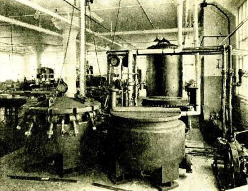
Paper Condensers - The Several Features of Manufacture Affecting Their Mechanical and Electrical Properties.
Drying and Impregnating Equipment.
(Radio for March, 1926)
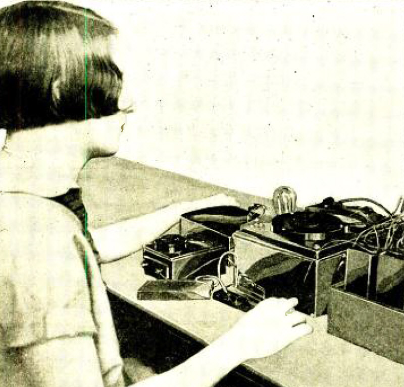
Testing a Condenser for Voltage Flash, Capacity and Leakage Resistance.
(Radio for March, 1926)
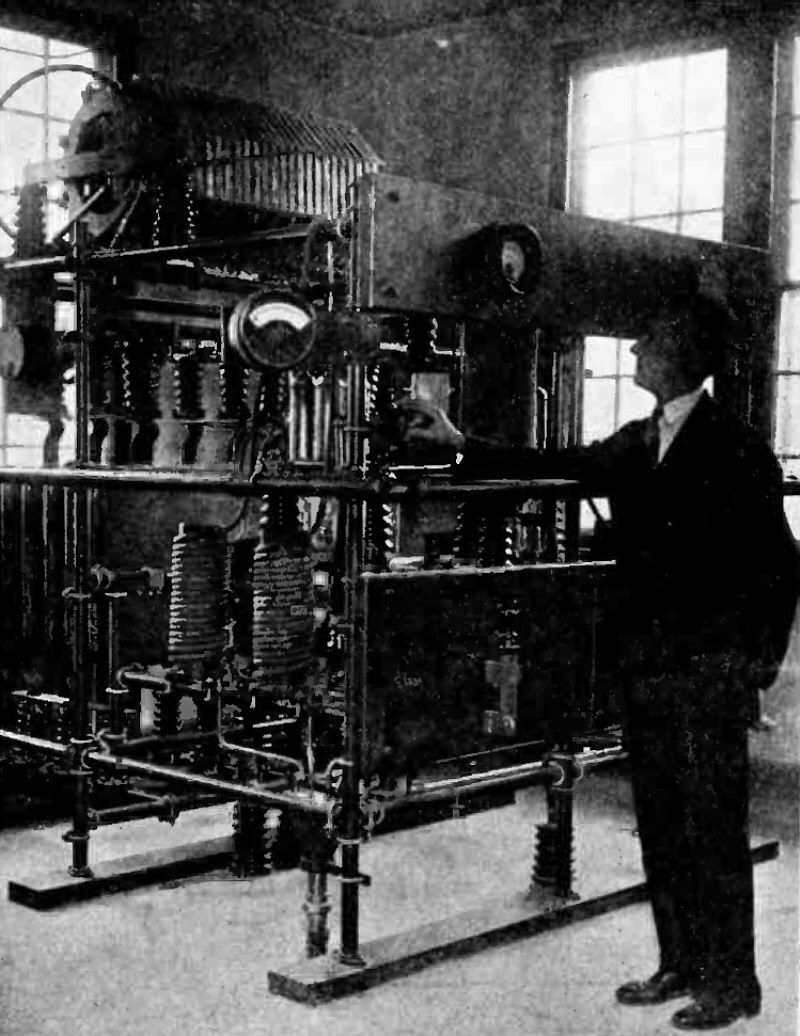
One of the Two 40-Kilowatt Transmitter at 2XAR, the Bound Brook, N. J. Station of the Radio Corporation of America.
(Radio for March, 1926)
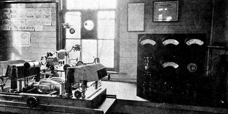
Signal Corps' 500 -Watt Short-Wave Transmitter at Presidio at San Francisco; 500 Cycle Plate Supply with Tuned-Grid Tuned-Plate Circuit.
Note Remote Control Relay on Left Side of Panel.
(Radio for April, 1926)
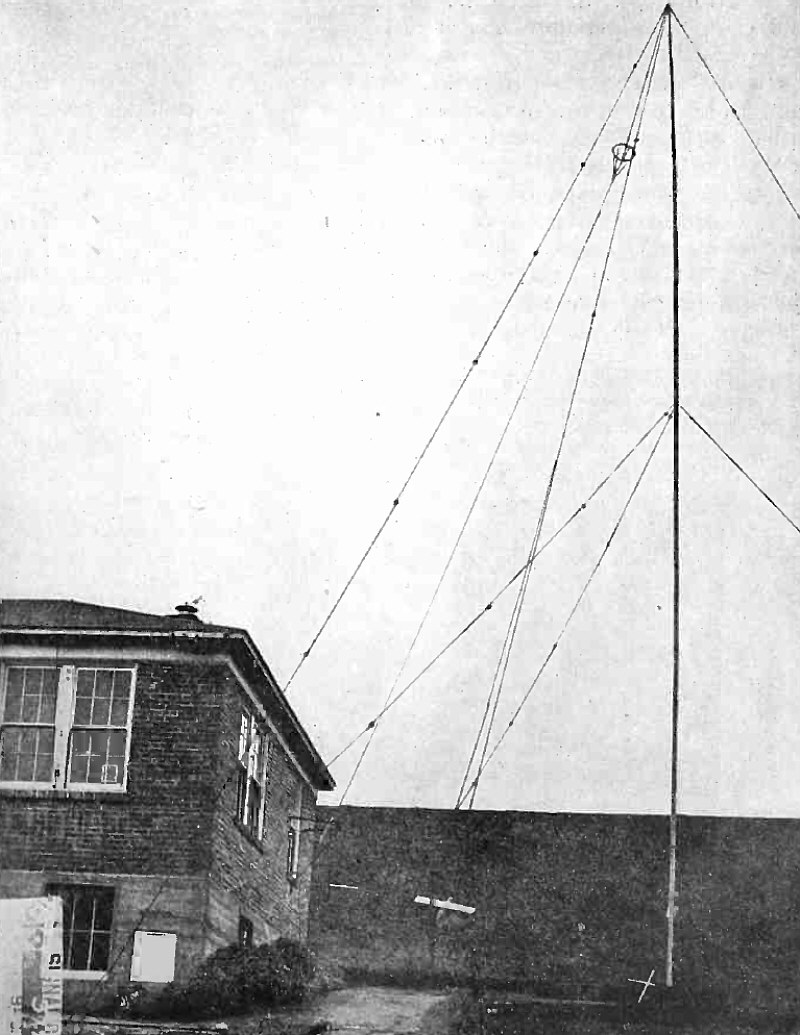
Sixty-Foot Mast Supporting 12,555 K. C. Antenna with Capacity Cage at Top.
(Radio for April, 1926)
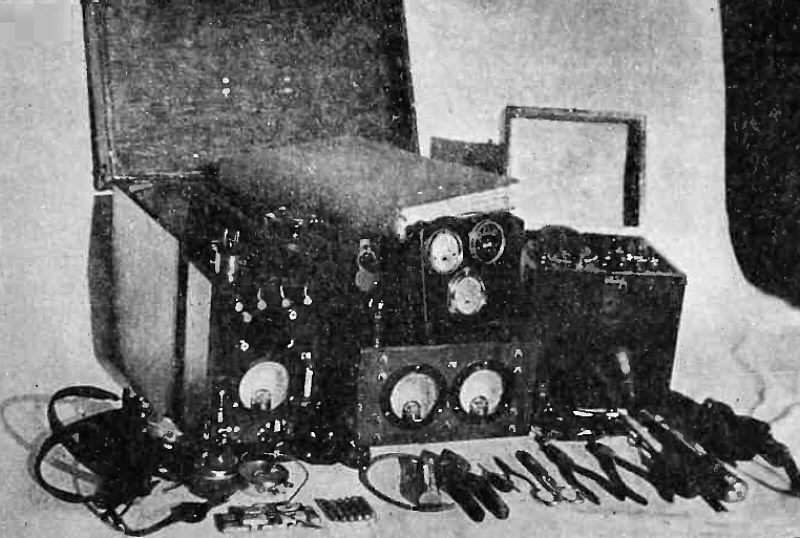
Portable Testing and Repair Outfit.
(Radio for April, 1926)
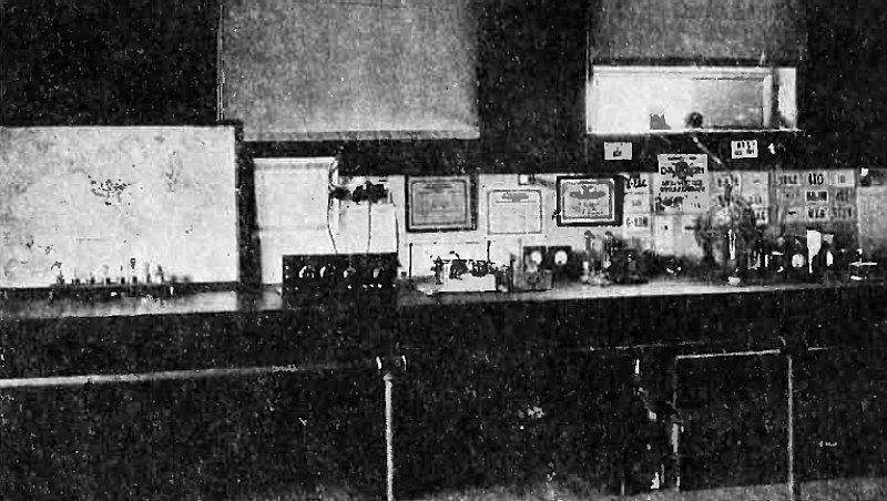
Short Wave Reflection Phenomena.
An Analysis and Simple Explanation of the Reasons Why Short Waves Travel Further Than Long Waves.
Station 8ZE-8XT, Physics Laboratory, Oberlin College, Ohio, Where Experiments Are Being Conducted.
(Radio for April, 1926)
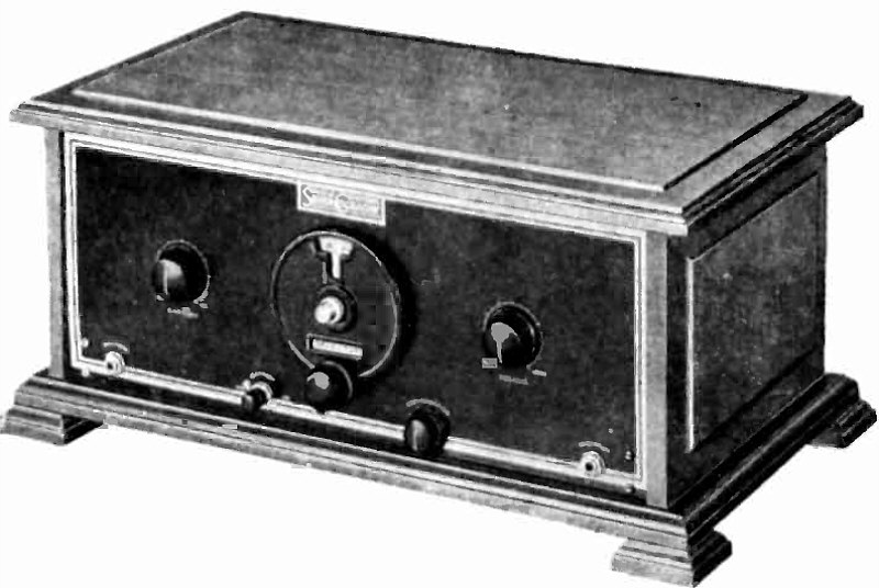
A Single Control All-Wave Four-Tube Receiver.
(Radio for April, 1926)

Circuit Diagram for Single Control All-Wave Four-Tube Receiver.
(Radio for April, 1926)
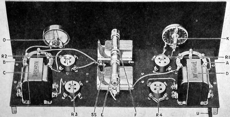
A Single Control All-Wave Four-Tube Receiver - Rear View Showing Top of Sub-Panel.
(Radio for April, 1926)
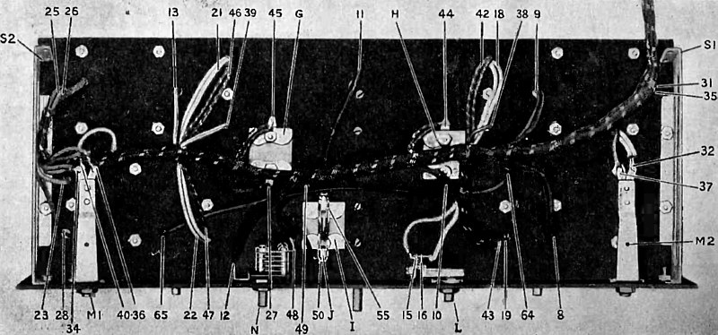
A Single Control All-Wave Four-Tube Receiver - Bottom of Sub -Panel.
(Radio for April, 1926)
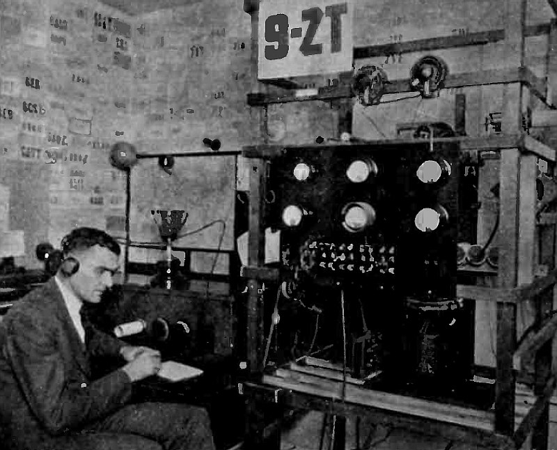
Receiving and Transmitting Equipment at Station 9ZT.
(Radio for May, 1926)
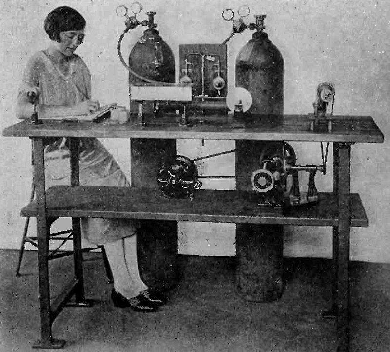
Why Do Radio Tubes Peter Out.
A Simple Explanation of the How and Why of Electron Emission.
Cleaning and Annealing Filament Wire. The fine tungsten wire, which is very snarly and stiff as it comes from the dies, is drawn over two mercury contact-points placed about 10 inches apart, to which current of sufficient potential is applied to heat the wire red-hot, thereby softening it and also burning off a grease that adheres to it from the drawing dies. The heated section of the moving wire is enclosed in a box, where it is continuously bathed in purifying gases fed from the steel cylinders.
(Radio for June, 1926)

American Committee in Charge of Program for International Radio Telegraph Conference to be Held at Washington Next Spring.
Members of the Committee are, from left to right: Frank McIntyre (State Department), Major J. O. Mauborgne (War Department), W. D. Terrell (Commerce Department), Chairman; L. A. Corridon (Commerce Department), W. M. Greene (State Department), E. M. Webster (Treasury), H. C. Moore (U. S. Shipping Board), and Lieut. Commander A. H. Tawresey (Navy).
(Radio for June, 1926)

Improving the Resistance or Impedance Coupled Amplifier.
Method of Installing R. F. Choke Ahead of Resistance Coupled Amplifier.
(Radio for June, 1926)
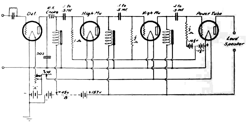
Circuit Diagram of Three-Stage Resistance Coupled Amplifier.
(Radio for June, 1926)
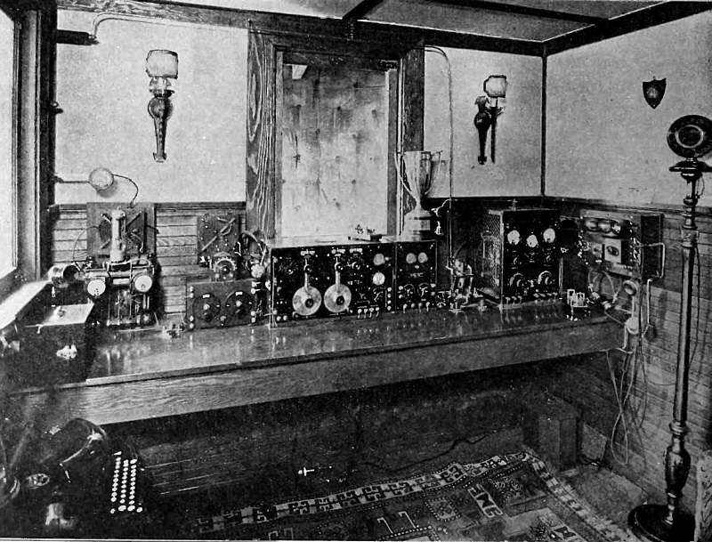
Radio Station 6AQA.
"A 50-watt short-wave transmitter that has been reported as heard in every state, England, France and Australia and its accompanying 100 watt phone transmitter is pictured herewith. 6AQA is owned and operated by an old-timer, George C. Tichenor, 1016 South Flower St., Los Angeles, Calif. From left to right in the picture, are: (omitting the land phone and noiseless typewriter) General Radio wavemeter, W. E. desk type microphone, short wave transmitter -40 to 80 meters CW only, short wave receiver -35 to 160 meters, Navy receiver and amplifier covering from 150 to 24,000 meters, antenna change-over switch, the 100 watt phone transmitter, speech input amplifier on the wall, and the microphone. Under the table is a Western Electric 25 B power amplifier which is used with the 540 AW disc type of speaker (on a table in another corner of room)..."
(Radio for June, 1926)
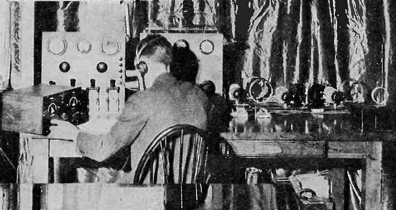
View of 2QA at Radio Show.
"As 2QA was the only outfit actually able to move traffic out of the Hotel Pennsylvania when the radio show was held there in connection with the New York convention of the Second District Executive Radio Council, a description of its construction and operation will interest many 'hams.' The circuit is a slight modification of the tuned plate, tuned grid circuits used at KFUH and 6XAO. Storage batteries are used for 300 volt plate supply. The key is inserted in series with the grid -leak to reduce key clicks. The blocking condensers have a capacity of .002 mfd..."
(Radio for June, 1926)
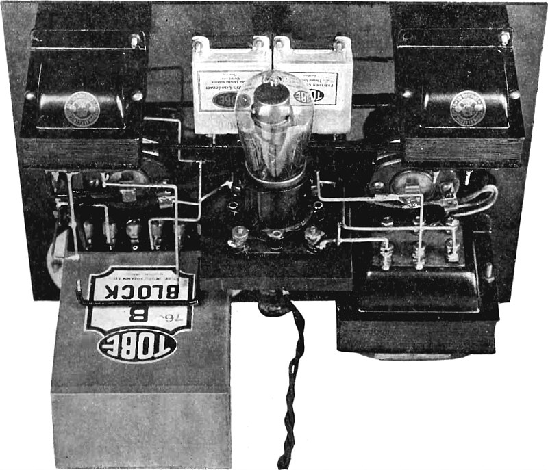
Panel Type Assembly, with Jefferson Transformers and Chokes, and Tube Condenser Block.
Article:
How to Build a Plate Current Supply Unit.
Detailed Directions for the Construction of Various Panel and Baseboard Models of Rectifier and Filter Systems.
"To meet the increasing demands for information regarding the best circuits and methods of assembly to be used in the construction of a plate current supply unit obtaining its power from the 110 volt a.c. house lighting circuits, a number of different models which have been made and tested in RADIO's laboratory are here illustrated and described. All of them deliver from 30 to 35 milliamperes at 150 volts and will meet the requirement of the UX-171, CX-371 power tube in the last stage of audio frequency amplification..."
(Radio for July, 1926)

Wiring Diagram for Raytheon Plate Supply Unit.
(Radio for July, 1926)

Pictorial Wiring Diagram of Panel Unit.
(Radio for July, 1926)

Main Assembly of Kellogg Type R. F. L. Receiver, Showing Single Control Features
Article: Four -Stage Tuned R. F. Receiver With Single Dial Control
(Radio for July, 1926)

Circuit for Microphone Amplifier.
(Radio for July, 1926)
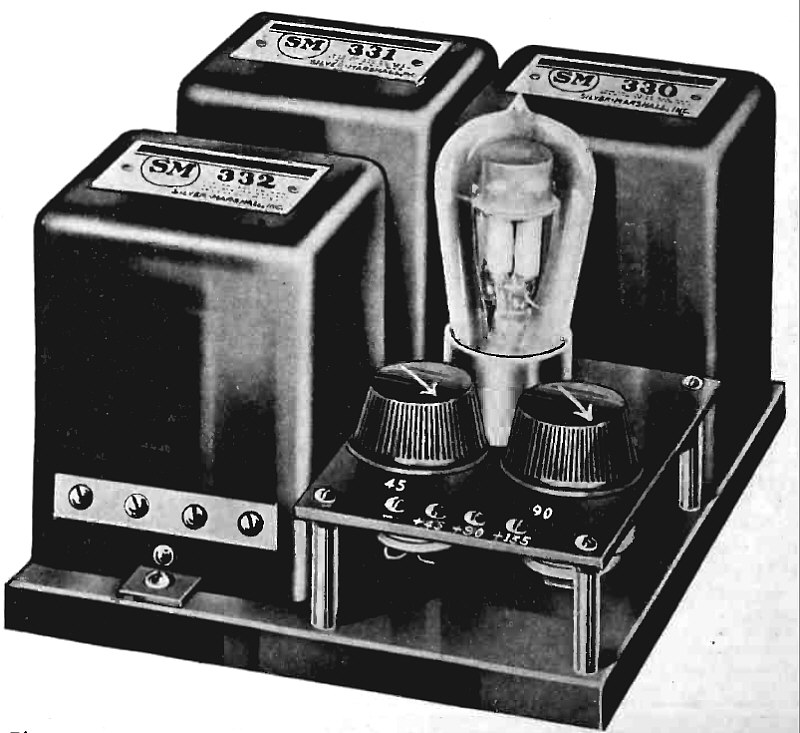
Plate Supply Unit for B-H Raytheon Tube Using Silver-Marshall Parts.
(Radio for July, 1926)

Complete Receiver as Installed in Hospital.
Article: An Automatic Multi-Channel Radio Receiver.
A Unit Developed for Use in Hospitals or Apartment Houses Where a Single Antenna Operates Several Receivers.
(Radio for August, 1926)

Circuit Diagram of Automatic Multi-Channel Receiver.
(Radio for August, 1926)

Transmitting End of Television Equipment.
Article: Some Notes On Television With Description and Illustration of First Crude Results Secured by Means of the Baird Televisor.
(Radio for August, 1926)

Original Picture and Image as Received with Televisor.
(Radio for Aygust, 1926)

Receiving End of Television Equipment.
(Radio for Aygust, 1926)
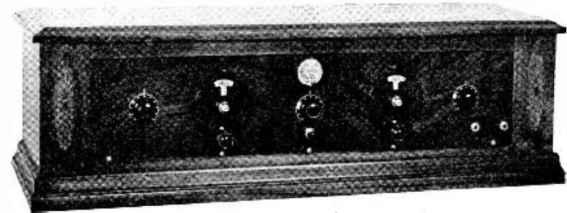
Panel View of Completed Infradyne Receiver.
Article: The Infradyne - A New and Efficient Ten-Tube Circuit Employing Three Stages of Intermediate Frequency Amplification at 3200 Kilocycles
(Radio for August, 1926)

Circuit Diagram of Infradyne Receiver. (Correction: 6T-299 should be 6T-199).
(Radio for August, 1926)

End View Showing Arrangement of Doughnut Coils.
(Radio for August, 1926)

Rear View of Infradyne Receiver.
(Radio for August, 1926)

Dr. A. Hoyt Taylor, of the Naval Research Laboratory, who supervised tests between 8000 and 27,000 kilocycles from the U. S. S. "Memphis," Call NISS, during a recent transAtlantic Trip. Many U. S., Australian and New Zealand amateurs were worked and much data secured on High Frequency Radio Phenomena.
(Radio for August, 1926)

Power Plant with Mazda Lamp Resistance Bank.
Article: A Complete Socket Power Receiver - Constructional Details for an "A", "B" and "C" Battery Supplanter and For the Latest Type of Browning-Drake Receiver.
(Radio for August, 1926)

Rear Fiew, Showing Baseboard Assembly.
Article: A Complete Socket Power Receiver - Constructional Details for an "A", "B" and "C" Battery Supplanter and For the Latest Type of Browning-Drake Receiver.
(Radio for August, 1926)

Kolster Loop Developed as Direction Finder for Radio Supervisor's Truck.
Article: An Accurate Direction Finder - Constructional Details for Uni -Directional Loop and Receiver for Locating Interference to Radiocast Reception.
(Radio for September, 1926)
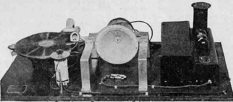
Dis-Assembled Parts of Panatrope.
Article: The Electrical Phonograph - A Description and Explanation of the Radio Principles Employed in Its Operation.
"As the recent improvements in phonographs represent an application of the principles developed in radio, it is deemed that those interested in radio will likewise be interested in the means whereby music from the electrical phonograph has greater volume than of old and a quality equal to the best obtainable from a first class radio receiver. The entire process of making and reproducing the records follows radio precedent. The selections to be recorded are picked up by a microphone similar to that used in broadcasting stations, amplified to the required degree by means of vacuum tubes, and then placed on a master record by an electro-mechanical recorder. Likewise the reproducing apparatus is entirely electrical, the sound being amplified in an audio-frequency amplifier like that used in a radio set and being transmitted to the listener by means of a loudspeaker identical with those used for radio..."
(Radio for September, 1926)

Schematic Wiring Diagram of Panatrope.
(Radio for September, 1926)

Panatrope - Rectifier -Amplifier Assembly, Showing Constructional Details.
(Radio for September, 1926)

Developing a New Long -Life Filament for a Low-Temperature Power Tube.
(Radio for October, 1926)
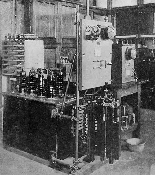
One of Many Testing Units in a Radio Research Laboratory.
(Radio for October, 1926)
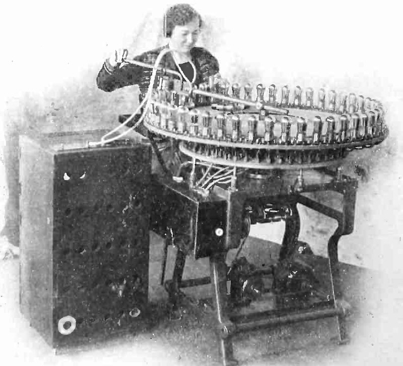
A Laboratory-Created Tube Ager and Bombarder Which Has Helped to Reduce the Manufacturing Cost of a 201A Tube to 28 Cents.
(Radio for October, 1926)

G-2ACI, Redford, England.
(Radio for October, 1926)
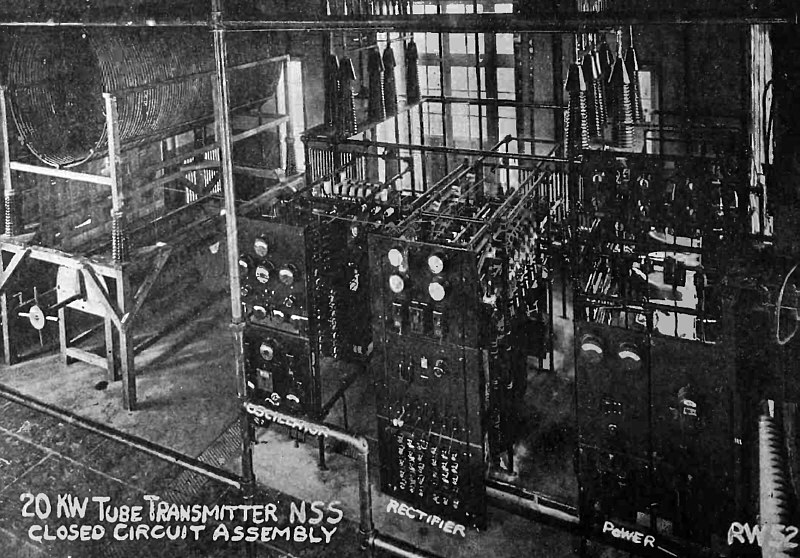
General View of 20 K.W. Tube Transmitting Equipment at NSS, Annapolis.
(Radio for November, 1926)
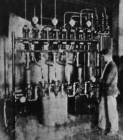
Rectifier tube Unit of 80 K.W. Tube Transmitter at San Diego.
(Radio for November, 1926)
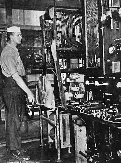
Control Panel of 20 K.W. Tube Transmtter at NAA, the U. S. Navy Station at Arlington, Va.
(Radio for Novebmer, 1926)
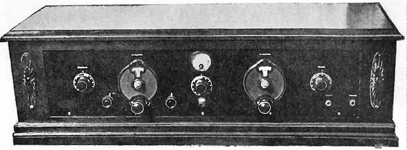
Front View of Sargent-Rayment Infradyne.
(Radio for November, 1926)
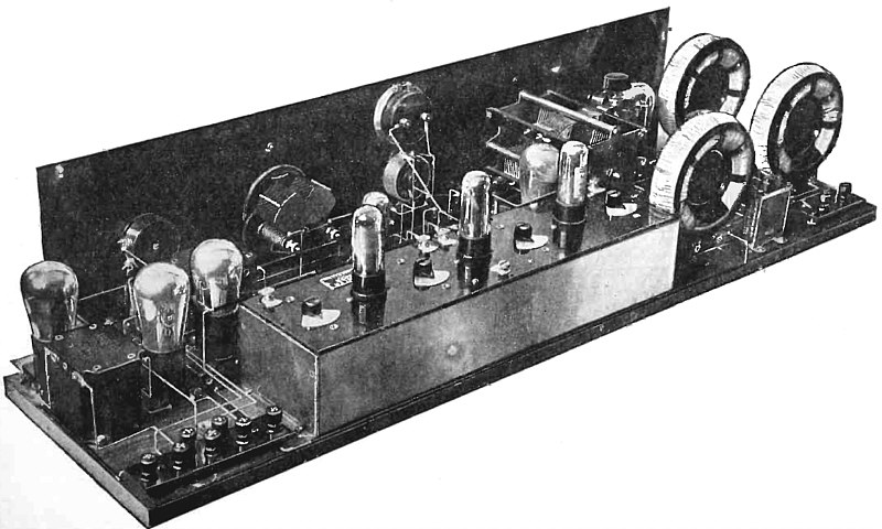
Rear View of Sargent-Rayment Infradyne.
(Radio for November, 1926)
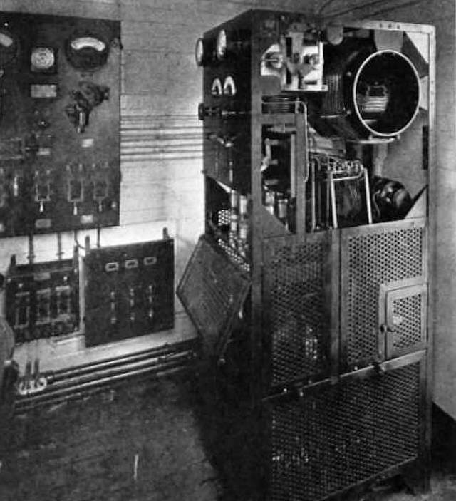
Master Oscillator, Power Amplifier, Transmitter on "Manoa"
(Radio for December, 1926)
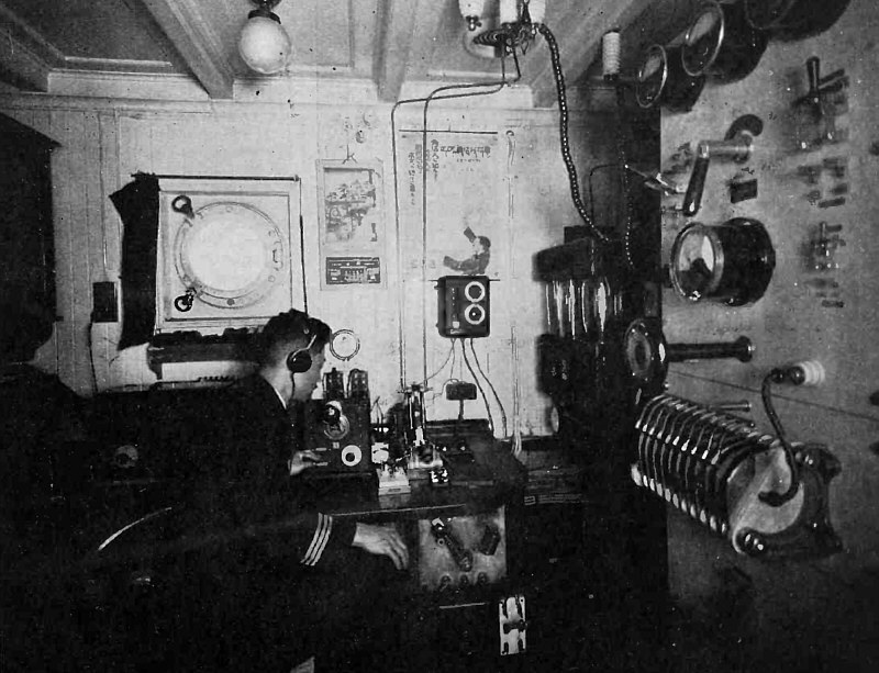
Telefunken Installation on "Shanyo Mara".
(Radio for December, 1926)

Converted Spark Transmitter on "Manos".
(Radio for December, 1926)
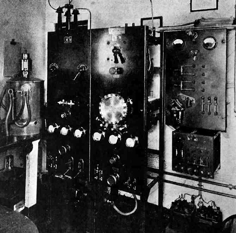
Federal Spark (on right) and Arc (on left) Transmitters on "Admiral Fiske" with Arc Converter ar Extreme Left.
(Radio for December, 1926)
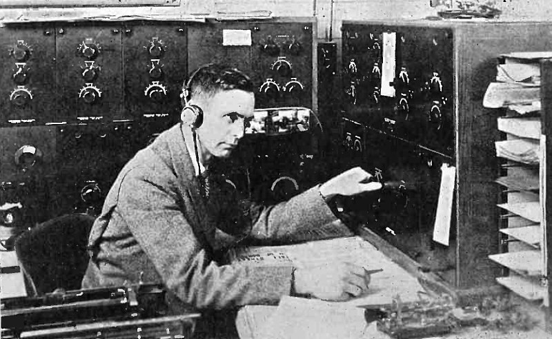
H. D. Watson.
(Radio for December, 1926)


