
Radioelektronics, may 1989, volume XL (120), 5'89
Cover: Even when designing shoes, a computer is used (Foto Siemens)
FROM THE COUNTRY AND FROM THE WORLD (cover page 2)
- Designing footwear using a computer
"SchuCAM" is the name of a computer program developed by Siemens for the footwear industry. Used by the largest European manufacturer of women's footwear - the Gabor company in Germany - it enables quick reaction to changes in fashion, reducing costs and shortening the development time. Difference to a conventional system? 40 years ago, the company released four new models per season, now - 250 to 350 new models in six months. - The new ITT-NOKIA compact disc player
The DP 7980 player is particularly distinguished by the container for 6 compact discs (CD), which allows you to play music for about 6 hours without interruption. It is possible to program 32 tracks in advance, repeat selected tracks, quickly search for the desired track. - Light signal splitters
Siemens informs that it has developed a technology for the production of glass plates in which fiber optic tracks with branched configuration are formed. The tile is 30 x 5 x 5 mm. The signal attenuation is approx. 0.3 dB / cm and additionally 0.3 dB at the branch. - Computer system as a translator
Experts from the West German concern Siemens have developed a computer system called METAL (Machine Evaluation and Translation of Natural Language) for "intelligent" translation of multilingual texts. Currently, the translation from German to English is ready, and the "reverse" version is in preparation - from English to German, as well as versions covering other languages: French, Spanish and Dutch.
ANNOUNCEMENTS (1)
ELEKTROACOUSTICS - MICROPHONES (3) (2)
- Special microphones
Of the many microphones with special features, we will only name a few.
Wireless microphones: The microphone cable connecting the microphone to the amplifier is especially inconvenient during performances of artists moving on the stage, passing from place to place, etc. Long time ago the idea arose to place a battery-powered radio transmitter in the microphone or close to it, and outside the stage or stage - setting the appropriate receiver, the output of which is normally connected to the mixer and amplifiers.
Limiting plane microphones: The limiting plane (acoustically) is e.g. the wall or floor of a studio or concert hall. Acoustic waves reflect off such a plane. If a microphone with a very small diaphragm diameter is placed in such a plane, it will exhibit special properties, mainly due to the fact that it does not interfere with the acoustic field in any way. Waves of different lengths come in from different directions, bounce, and travel on. Of course, the directivity characteristic of such a microphone is in the shape of a hemisphere. The figure shows this type of microphone. These microphones are generally designed as condenser microphones. They are distinguished by a very natural sound perception and a good reproduction of the acoustic atmosphere. They are used in studios to pick up a solo instrument (e.g. piano) or small orchestral ensembles.
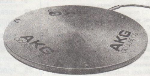
Studio condenser microphone "limiting plane microphone" - AKG type C562BL
- Selected recommendations for the use of microphones
The microphone perceives changes in sound pressure that cause the diaphragm to vibrate. A human being hears with two ears and immediately subjected the received waveforms to extremely complex processing in the brain. It can be said that the microphone "hears" objectively and the human hears subjectively, and these are completely different ways of hearing. You have to remember about this when using microphones.
In the phonographic and radio studio, an acoustician has a lot of resources at his disposal, enough time for rehearsals and the possibility of using the multitrack recording technique, i.e. preparing the sound material from which the final musical product is made. An extensive knowledge of microphone studio technique has arisen, which is constantly enriched as experience accumulates and new technical means are introduced. This activity is the domain of a fairly small group of specialists. - Power
Condenser microphones require an electrical source. Several solutions are used.
Condenser studio microphones are supplied in a standardized manner by a derivative (phantom) wire made of the two "signal" wires and a shield connected to the ground of the microphone.
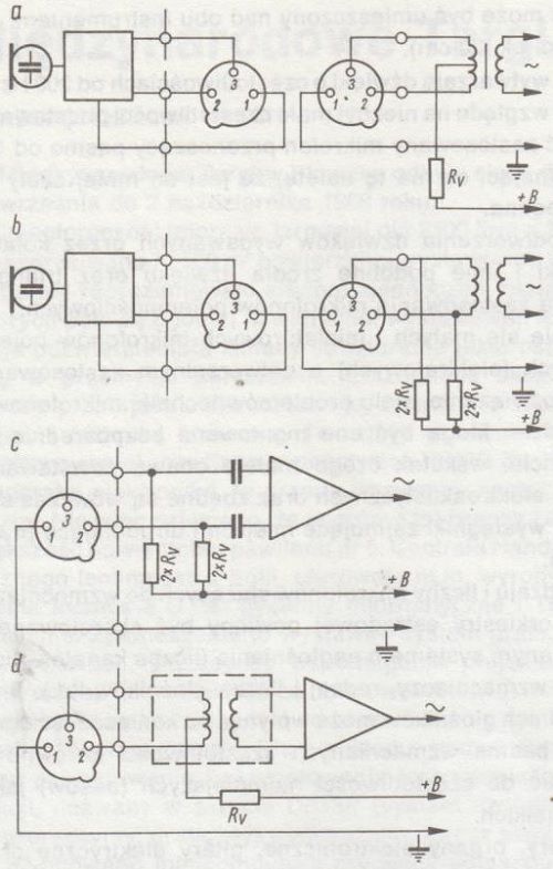
Diagrams of powering condenser microphones through a derivative wire path.
- Cables as well as plugs and connection sockets
The microphone cable contains two insulated multi-core conductors (0.2 to 0.6mm2, depending on the type of cable), a shielding braid (often double) and an outer protective layer. The microphone cables are made in such a way that they do not become entangled or looped. The outer diameter of the cable is 4 ÷ 7 mm.
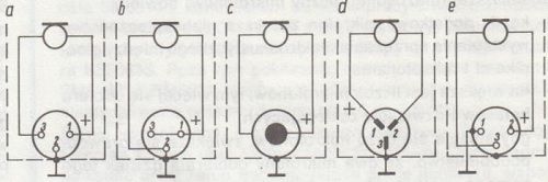
Diagrams of connecting microphones to different plugs
- a - DIN microphone plug (WM-345) symmetrical connection
- b - DIN microphone plug (WM-345) asymmetrical connection
- c - 6.3 mm "finger" plug, asymmetrical connection
- d - special plug (DIN 41624), symmetrical connection
- e - Cannon XLR plug, symmetrical connection
UNUSUAL ILLUMINOPHONIC DEVICE (5)
The characteristic features of the illuminophony device described in the article are: the use of Siemens UAA180 integrated circuits (national equivalent of UL1980N) in the device,
used to light the light-emitting diodes in the control indicators, the use of optoelectronic coupling between the control members and the output light member of the device, and the design of light sources as three light bars of varying height. The power of the device may vary, depending on the bulbs used and their power supply.

Schematic diagram of the illuminophonic device
TAPE RECORDER CASSETTES IN SUMMER (6)
The summer period is approaching, and with it trips on trips and holidays with various types of cassette recorders. Therefore, it is worth paying attention to a few rules that will protect us against damage to the cassettes or deterioration of their performance.
MICROPROCESSOR TECHNIQUE - TUNER MICROPROCESSOR CONTROLLER (2) (6)
- Equipment
Description of the principle of operation of the frequency synthesizer - Analog module
- Remote control
RTV TECHNIQUE- SATELKITE TELEVISION (2) (9)
- Receiving devices
Television signals retransmitted by satellites can be received by many terrestrial receiving devices cooperating directly or indirectly with home TV sets.
MEASUREMENT - CIRCULAR SMITH CHART (2) (12)
As in the Gaussian coordinate system, also in the Smith system, each point of the plane represents a complex resistor according to its real and imaginary value. The real values are plotted on the horizontal axis (system diameter), positive imaginary values on the upper half of the circuit's circumference, negative imaginary values on the lower half of the circular Smith system, impedances at the intersection of the real and imaginary curves.
SCHEMATIC DIAGRAMS - TV SETS NEPTUN 471, 471A, 671 (15)
Neptun 471, 471A, 671 TV sets, produced since 1984 in Gdańskie Zakłady Elektroniczne Unitra - Unimor, are designed to receive black and white television programs broadcast in bands from I to V according to the DK standard.
OTV Neptun 471, 471A, 671 are stationary class II TV sets with safe cathode ray tubes, powered from the mains with alternating voltage 220 V + 5% / - 10%, 50 Hz, intended for operation in moderate climate conditions.
- Technical data
- Schematic description

Diagram of the MOS FET TJ01M-050145 head

Diagram of the bipolar head VTJ 01M-564554 (N1 and N104 - ferrite chokes)
- Module UMP-1006
- Audio track
- Video track
- Horizontal synchronization system
- Horizontal deflection system
- Vertical deflection system
- Power system
THE YOUNG ELECTRONICS CLUB - A GUIDE OF ELECTRONICS. TRANSISTORS (2) (22)
In connection with the main parameters, the classification of transistors into individual types was adopted. It is most convenient to use a catalog in which transistors are classified primarily by main parameters and, to some extent, by fields of application.
In the CEMI Scientific and Production catalog of the CEMI Semiconductor Center, in accordance with the internationally accepted system, the second letter of the marking determines the type of transistor according to the following code:
- C - transistors of low and medium power, low frequency,
- D - low frequency power transistors,
- F - low power, high frequency transistors,
- L - high frequency power transistors,
- S - impulse (switching) transistors, low power,
- U - pulse power transistors.

Sketches of the more common types of transistor housings
RADIO COMMUNICATION - DEVICE FOR REMOTE CONTROL OF MODELS (23)
The article describes the parameters, construction and operating principle of a model remote control device called MFFS 27 MHz, manufactured by VEN PIKO Sonnenberg (East Germany). It is the successor to the Signal FM-7 device, previously produced and sold also in Poland (described in "Re" no. 1/1986). In the near future, the MFFS 27 MHz set is to be sold by the Central Scouting Store.

Schematic diagram of the electric servo system
MFFS 27 MHz is designed for remote control of flying and floating models and motor vehicles. The average range of the device does not exceed 1 km on land, in water or when controlling a flying model. When controlling models on land, the range is the smallest as it depends on the type and shape of the terrain.
POLISH SHORT WAVE (27)
- From the life of the Association,
- Interesting fact from the world of ham radio,
- A new form of PZK membership,
- "Worked Copernicus Towns Award" diploma.
ELECTRONIC COMPONENTS - LA3210 IC (29)
Fulfilling the requests of readers who bought Sanyo LA3210 integrated circuits in Bomisu stores, we present information about this system. The LA3210 integrated circuit functions as a correction amplifier for a cassette deck with automatic recording level control (ALC).

Electrical diagram of the LA3210 chip

Electrical diagram of a correction amplifier for a tape recorder
IDEA AND IMPLEMENTATION - CONVERTER (29)
In general, there is a problem with powering devices that require DC voltage from an AC network, but the reverse situation also occurs. Here is one way to do this.

Diagram of a low-power DC to AC converter
MISCELLANEOUS - INTERNATIONAL TECHNICAL FAIR PŁOWDIW'88 (30)
ANNOUNCEMENTS (32)
FROM THE COUNTRY AND FROM THE WORLD (33)
- 100 years of a magnetic data storage medium.
- Spontaneous damage to compact discs.
- New British Satellite.
- Chip card instead of a ticket.
- Active sensor indicating damage to the display glass.
- Remote car door opening.
You end up looking for keys in pockets or purses and struggling with the frozen lock on the car door.
")
")
")
")
")