Home
How to make a push-pull transformer for a low frequency amplifier
- Details
- Category: Radioamator i Krótkofalowiec
- Hits: 5388
![]()
How to make a push-pull transformer for a low frequency amplifier
Author: Ryszard Zarzecki
Radioamator i Krótkofalowiec, Rok 19, Sierpień 1969r., Nr 8
(Radio amateur, Year 19, August 1969, No. 8)
When designing push-pull amplifiers, it is often difficult to acquire or manufacture a suitable output transformer. The Soviet monthly "Radio" no. 2/1967 presents a simple method of making such a transformer. For this purpose, two identical, "normal" output transformers are needed (for example from a "Pionier" type receiver). Metal clamps and a package of simple plates closing the core should be removed from these transformers, and plates of the "E" type should be left together with the bodies with windings placed on them.
Transformer cores with windings should be put together as shown in Fig. 1.
![]()
Fig. 1.
In this way, the assembled transformers are connected and squeezed with a new metal clamp, and then - the beginning of the anode winding of one transformer is connected to the end of the anode winding of the other transformer (Fig. 2).
Read more: How to make a push-pull transformer for a low frequency amplifier
Amateur acoustic amplifier "Melodia"
- Details
- Category: Radioamator i Krótkofalowiec
- Hits: 5449
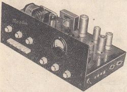
Amateur acoustic amplifier "Melodia"
Lech Krzymowski
Radioamator i Krótkofalowiec, Rok 20, Wrzesień 1970r., Nr 9
(Radio amateur, Year 20, September 1970, No. 9)
The amplifier, the diagram of which is shown in Figure 1, is not a revelation or a novelty, but due to the results obtained, it may be of interest to amateurs of good music and enthusiasts of small music bands.
The use of such units as a 3-channel mixer system and a key switch for changing the amplifier's frequency characteristics with simultaneous smooth adjustment in the range of extreme frequencies of the acoustic band gives good results, which was found using the ZK-120 tape recorder and a turntable. The results were incomparable with the capabilities of average systems, even factory production. Also the attempt to use the amplifier by the small music band was positive.
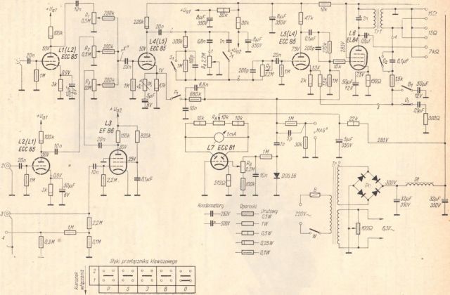
Fig. 1. Schematic diagram of the "Melodia" acoustic amplifier
(The drawing is large so you can copy it, for example to a graphics program and view the details)
The block diagram of the amplifier in Figure 2 explains the purpose of each stage of the circuit.
We are building a stereo amplifier
- Details
- Category: Radioamator i Krótkofalowiec
- Hits: 5562
We are building a stereo amplifier
Eng. Zbigniew Faust
Radioamator i Krótkofalowiec, Rok 22, Maj 1972r., Nr 5
(Radio amateur and amateur radio operator, Year 22, May 1972, No. 5)
(Prepared on the basis of "Funktechnik" no. 23, 24/1965 and no. 2/1966)
Here is a description of the construction of a stereo amplifier intended for cooperation with a stereo turntable. The amplifier has two channels: left and right. Each channel consists of an input stage, volume and balance controls, and an output stage. In the input stage, the weak signals from the turntable are pre-amplified, as well as the correction of the frequency characteristics of the reproduced recordings from gramophone records by appropriate raising or lowering of bass and treble. The volume control system allows you to continuously change the sound strength of recordings, while the balance control allows you to equalize the playback volume of both channels. The output stage is no different from a similar mono amplifier stage.
Taking into account the design, the amplifier has been divided into 3 parts:
- tone correction system (preamplifier),
- two-stage power output amplifier,
- power supply system.
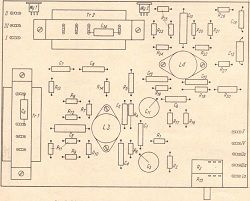
The individual elements of the system are mounted on separate bakelite plates, thanks to which experimenting with the system is very easy.
Basic technical parameters:
- Output power: max 2×4W
- Sensitivity: about 100mV
- Frequency response: 5Hz÷20kHz (-3dB)
- Nonlinear distortions: less than 5%
- Power supply: 220V/50Hz
- Power consumption: about 80W.
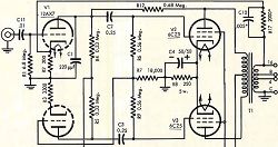
SOUND TONE CORRECTION
The circuit includes two levels of voltage amplification in each channel and a tone control system, separately for low and high tones.
The schematic diagram of the system is presented in Fig. 1. Both amplifier channels are the same and therefore it is enough to describe only one of them. The input from the stereo turntable passes through the standardized input jack [We] and the coupling capacitor C1 to the sound level controller R1, and then through the capacitor C2 to the tube control grid L1a. The grid leakage resistor is 1MΩ. There is a resistor R6 in the cathode circuit of the electron tube to generate the grid bias voltage, blocked by the capacitor C4. The signal amplified in the anode circuit is fed through the resistor R4 and the capacitor C6 to the tone control system. So that the treble is not weakened too much, the R4 resistor is bypassed by the C5 capacitor. In the first amplification stage, there is furthermore a feedback between the anode and the grid of the tube L1a (resistor R5). Due to this coupling, a more linear transmission characteristic and a lower coefficient of non-linear distortion are obtained.
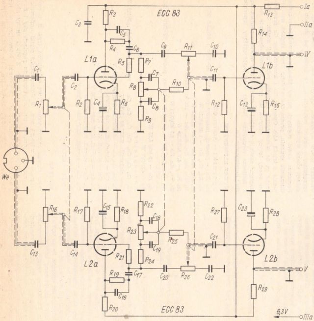
Fig. 1. Schematic diagram of the tone correction system
The tone control system consists of two RC circuits. The first circuit includes elements R7R8R9C7C8 for bass adjustment, and the second circuit (C9R11C10) allows the treble response to be changed. The R10 resistor decouples the bass control circuit from the treble control circuit.
An Amplifier Using New 6CZ5's
- Details
- Category: Audio USA
- Hits: 6878
An Amplifier Using New 6CZ5's
Nathan Grossman
AUDIO, JULY, 1958, VOL. 42, No. 7 (Successor to RADIO, Est. 1917)
Most experimenters have sufficient equipment in the "surplus" department to construct this simple amplifier which gives good performance in a small package
The 6CZ5, a new RCA miniature power tube, holds much promise for the art of audio power amplification. This tube is not to be confused with the 6AQ5, or English 6BQ5, both of with it resembles in construction and purpose. It is not interchangeable with them.
It has the same filament, plate and screen, and load characteristics as the 6V6, of which the 6AQ5 is the miniature type, and costs about the same. However, the other characteristics are different and provide a considerable improvement over tha latter types. The negative bias on the signal grid and the transconductance are about 15 per cent greater and the power output about 20 per cent greater for a plate voltage of 250. In push-pull operation the 6CZ5 resembles the 6L6 in that it generates a low percentage of odd harmonics and can be operated as a pentode with a plate voltage of 350. Under this latter circumstance and with 280 volts on the screen, a bias of -23.5 volts on the signal grid, and a plate-to-plate load of 7500 ohms, two 6CZ5's are rated by the manufacturer to deliver 21.5 watts of audio power and with only 1 per cent of harmonic distortion.
This adds up to lower supply requirements, lower distortion, lower all around cost, and higher power output. To try a pair of 6CZ5's the writer built an amplifier from parts in the junk box including a husky output transformer which was manufactured about 20 years ago. To avoid expense in obtaining good voltage regulation, the writer used a large bleeder and worked the amplifier half way between the recommended pentode and the lower-plate voltage tetrode operation. With 325 volts from plate to cathode, the results proved better than expected. The plate voltage did not vary from minimum to maximum power output, and total variation of the screen voltage was only 3.5 per cent.
The 88-50 - a Low-Distortion 50-Watt Amplifier
- Details
- Category: Audio USA
- Hits: 6751
The 88-50 - a Low-Distortion 50-Watt Amplifier
Audio, January, 1958, Vol. 42, No. 1 (Successor to RADIO, Est. 1917).
W. I. HEATH and G. R. WOODVILLE
With harmonic distortion of less than 0.5 per cent throughout most of the audio spectrum, this 50-watt amplifier is comparatively simple in construction and requires only ordinary care in wiring.
For audio amplifiers of medium power, the KT66 output tube became well known with the Williamson amplifier, and its reputation for reliability has made it much sought after in "off - the - shelf" high - fidelity amplifiers, as well as in home - built kits.
From the same stable there now follows a new tube, the KT88, a pentode with a higher plate - to - screen dissipation of 40 watts, and a higher mutual conductance of 11 mA per volt (11,000 microhms).
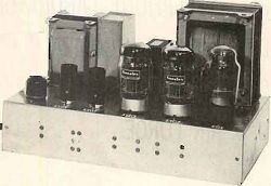
The KT88 makes it possible to use familiar circuit techniques to build audio amplifiers giving the higher power output needed to handle the "peaks" in high - fidelity reproduction at home, or for public address equipment. This higher output is obtainable without using a plate voltage higher than that available from standard components. The KT88 achieves this by virtue of its lower plate impedance. For example with cathode bias, 30 watts of output power is obtainable with a plate supply of only 375 volts, compared with 425 volts required by the KT66. The maximum power obtainable with cathode - bias from a pair of KT88's is slightly over 50 watts with a supply voltage of 500 volts. This article describes the design and construction of such an amplifier; a second article will give similar details of a matching preamplifier. They are shown together in Fig. 1.
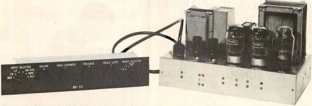
Fig. 1. External view of amplifier and preamplifier described by the author. This installment covers only the 50-watt power amplifier.
The complete amplifier, the "88-50" has been designed to give a high performance and a complete range of input and control facilities without complicated networks or unusual components. It is therefore reasonably economical to construct. With its preamplifier it will reproduce from any programme source such as radio tuner, magnetic or crystal phonograph pick-up, microphone, or direct from a magnetic tape replay-head. A rotary switch selects the required input circuit and at the same time adjusts sensitivity and frequency correction to the required playback characteristic. The preamplifier is separate from the power amplifier and is connected to it by a flexible cable. Its controls include a loudness control, a presence control, and a treble-slope control, all these being continuously variable with a flat position around half-way. A wafer switch preselects the frequency at witch the treble-slope control operates. To avoid one of the biggest gremlins of high-fi apparatus a rumble filter using an attractively simple circuit is incorporated in the preamplifier.
How an Output Transformer Causes Distortion Part 2
- Details
- Category: Audio USA
- Hits: 8649
How an Output Transformer Causes Distortion
In Two Parts - Part 2
Audio, March, 1957, Vol. 41, No. 3 (Successor to RADIO, Est. 1917).
Norman H. Crowhurst
The operation of audio transformers has long been surrounded with an aura of mystery. This article distinguishes the different forms of distortion an output transformer can produce, and gives some simple measurement methods.
As this distortion due to reactive loading is quite similar to the varietes that a transformer causes at high frequencies we will consider both together. (A) in Fig. 8 shows the practical circuit of an output transformer while (B), Fig 8 shows the load seen be the output tubes.

Fig. 8. Practical and equivalent circuit of output transformer for high frequency response: (A) actual circuit: (B) equivalent plate load for output tubes.
Directly shunting from plate to plate is the primary capacitance of the transformer. The load resistance gets stepped up by the ratio N2 but, due to leakage flux that gets between the primary and secondary windongs, there is an effective inductance between ths load and the tubes, shown in the equivalent circuit of (B), Fig 8 as leakage inductance.
The winding capacitance has the same properties as any other capacitance in a circuit. A leakage inductance is precisely similar to any air-cored inductance: it cannot introduce distortion of itself.
However, if leakage inductance is the dominant reactance at the high-frequency end, then the load resistance, referred back to the primary will look like a resistance with an inductance in series. If the output tubes cause distortion with series reactance added to the load resistance, then this kind of transformer will appear to cause distortion.
In other amplifiers, distortion may appear more rapidly when a reactance is added in parallel with the load resistance. In this case a transformer, in which the winding capacitance is the dominant reactance at the high frequency end, will show distortion more rapidly.
Read more: How an Output Transformer Causes Distortion Part 2
How an Output Transformer Causes Distortion Part 1
- Details
- Category: Audio USA
- Hits: 10015

How an Output Transformer Causes Distortion
In Two Parts - Part 1
Audio, February, 1957, Vol. 41, No. 2 (Successor to RADIO, Est. 1917).
Norman H. Crowhurst
The operation of audio transformers has long been surrounded with an aura of mystery. This article distinguishes the different forms of distortion an output transformer can produce, and gives some simple measurement methods.
The use of audio transformers has long been depreciated on the grounds that they cause distortion. In fact the output transformer seems to be almost the sole survivor of the species and many attempts have been made to do without even this. A few amplifiers have been designed to dispense with the output transformer, apparently in the belief that the output transformer is the principal remaining cause of distortion.
Careful analysis will usually show that the tubes introduce more distortion than the output transformer would have and that that a well-designed amplifier using the conventional output transformer can achieve a much lower order of distortion than is possible without one.
A few simple facts about transformers seem to get overlooked: when the tube curvature causes distortion it distorts all frequencies; but the distortion a transformer causes due to nonlinearity of its magnetizing current is concentrated at the low-frequency end. The worst transformer made will not distort the middle frequencies and the way it distorts at both lower and higher frequencies is one of the things we shall clarify in this article.
But, surely, someone will say, a transformer can cause distortion at middle frequencies? "I remember replacing a transformer, and the replacement would not give so much power without distortion as the original did." Doesn't this prove that the transformer distorts at the middle frequency? To understand the cause of this experience, let's consider the effect of transformer efficiency on amplifier performance.
The Importance of Efficiency
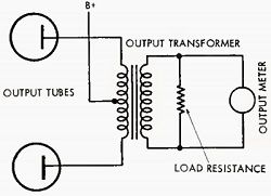
Amplifiers are rated to give a certain maximum output, determined by the performance of the output tubes. However, the output power is always measured on the secondary side of the output transformer, as shown at Fig. 1.

Fig. 1. Usual method of measuring output power consists of calculating the watts dissipated in a load resistor connected to the secondary of the output transformer. While this is the available power output, the output tubes actually deliver a little more than this.
A good output transformer is probably about 95 per cent efficient. This means that, if the amplifier gives 50 watts output, measured on the secondary side of the transformer, there must be nearly 53 watts output delivered to the primary side from the output tubes. The output tubes are having to give nearly 53 watts output for us to measure a good 50 watts.
Read more: How an Output Transformer Causes Distortion Part 1
Two-stage mains powered amplifier
- Details
- Category: Radioamator i Krótkofalowiec
- Hits: 6502
Two-stage mains powered amplifier
Radioamator i Krótkofalowiec 1961/11. Author: K.W.
(A corner for beginner radio amateurs)
The simple one- and two-stage battery amplifiers described in the previous issues of the magazine helped us to get acquainted with the basic circuits of this type of amplifiers. We must say, however, that battery power, apart from its specific advantages, has a major disadvantage: it is uneconomical. Therefore, wherever possible, radio equipment is powered from AC power circuits.
AC powered amplifiers, popularly known as "mains" amplifiers, differ from battery amplifiers in that, apart from the actual amplifying circuit, they are equipped with a power module, usually composed of a mains transformer, a rectifier tube and a rectified voltage smoothing filter. Some details about the layout and operation of the power supply were given in the previous issue when discussing the design of the power supply, intended for cooperation with a two-stage low-frequency amplifier. The power supply is usually constructed as one unit with the amplifier or receiver system (e.g. radio receivers), and only in special cases it constitutes a separate element. The latter solution is used, for example, in the popular tourist receiver "Szarotka".
There is also a second, fundamental difference between a mains and a battery amplifier: the use of other types of tubes. This issue requires further discussion due to its crucial importance.
As we remember from the short explanation of the principle of operation of the electron tube ("Radioamator" No. 5/61), the cathode is the source of electron emission inside it. In the case of battery-operated tubes, it is simply a thin filament, heated to an appropriate temperature. The design of the cathode of the vacuum tube adapted to AC power is more complex.
Figure 1 shows us in cross-section the cathode of such a modern vacuum tube. It is an "indirectly heated" cathode. As we can see, it consists of two basic elements: an electric heater made in the form of a spiral of resistance wire and the actual cathode. The latter, usually made in the form of a ceramic tube, is covered on the outside with a suitable substance which, when heated to an appropriate temperature, emits electrons. As you can see, the filament circuit does not directly participate in the work of the amplification circuit.

Fig. 1. Cathode of an indirectly heated electron tube (cross-section)
Indeed, the fragment of the amplifier diagram with the tube in question shown in Fig. 2 has a filament circuit completely independent of the rest of the circuit.
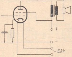
Fig. 2. Part of the schematic diagram of an amplifier with an indirectly heated electron tube
Now we can present our readers a schematic diagram of one of the mains amplifiers. As shown in Figure 3, it is a simple and economical system, as it uses only one modern ECL82 electron tube.
Stereo amplifier
- Details
- Category: Młody Technik
- Hits: 7080

Stereo amplifier
Młody Technik 1972/09 (Young Technician 1972/09)
MSc. Franciszek Lesiak
The amateur construction of a high-quality stereo amplifier is very difficult and requires a lot of theoretical knowledge, practical skills, as well as considerable financial resources. Therefore, we offer those who are interested in making a simplified high-quality amplifier, not necessarily HI-FI, but with better parameters than the amplifiers described so far in the "Young Technician" magazine.
The device is characterized by a significant output power sufficient to amplify a large room, e.g. a common room, club, etc., a wide band of transmitted frequencies and a low coefficient of non-linear distortions.
The audio set consists of an amplifier and two loudspeakers. Basic data of the amplifier:
- 2 x 10 W output power with a distortion of 1.5%,
- Frequency response 30 ÷ 15,000 Hz,
- Sensitivity 0.2V,
- Tone adjustment:
- ± 10 dB at 50 Hz,
- ± 10 dB at 10 kHz,
- Dimensions 440 × 230 × 110 mm.
The schematic diagram of the amplifier is shown in Fig. 1. Each channel of the system contains a three-stage power amplifier in a push-pull circuit built on EL84 tubes, and also a gain and tone control system.
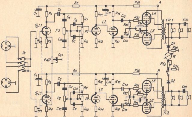
Fig. 1. Schematic diagram of the amplifier
The input signal from one of the two input sockets goes through a switch Pr to the potentiometer P1 used to adjust the volume, and then to the grid of the tube L1, which is the first stage of voltage amplification. Both cathodes of the tube L1 are connected to the leads of the potentiometer P4, the slider of which connects to the capacitor C21.
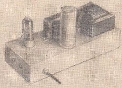
Assembling the simplest low-frequency tube amplifier (II)
- Details
- Category: Radioamator i Krótkofalowiec
- Hits: 7457

Assembling the simplest low-frequency tube amplifier (II)
Radioamator i Krótkofalowiec 1961/06. Author: K.W.
(A corner for beginner radio amateurs)
The previous issue of the magazine gave novice radio amateurs a description of the operation and construction of a tube amplifier with a very simple design with an input transformer. At the same time, a diagram of a similar circuit equipped with a potentiometer for volume control was presented. Now, as announced, we will discuss the amplifier layout in this modified version, with assembly instructions and drawings as usual. Undoubtedly, they will facilitate the correct construction of this simple amplifier.
The operation of the amplifier, the diagram of which is shown in Fig. 1, is of course analogous to the operation of the previously discussed circuit, and we refer to it all Readers interested in its construction.
Fig. 1. Schematic diagram of the amplifier
The input circuit of the system requires a separate discussion, not only because it is still unknown to us, but above all because of its great popularity. As we know, each radio receiver or amplifier is equipped with a knob with which you can adjust the volume of the received broadcast or playback. This knob is nothing more than a component part of an element called a potentiometer.
Read more: Assembling the simplest low-frequency tube amplifier (II)
Page 3 of 10
Select your language
")
")
")
")
")