Home
Speaker amplifier "3L"
- Details
- Category: Radioamator
- Hits: 8537
Speaker amplifier "3L"
eng. Czesław Klimczewski
Radioamator, Rok III, Styczeń 1953r., Nr 1 (Radioamateur, Year III, January 1953, No. 1)
In issue 11 of our magazine there is a description of a loudspeaker pickup (amplifier) with two electron tubes operating in a push-pull arrangement using a transformer that controls these tubes. As it is not always possible to purchase such a transformer on the market, winding it presents a certain difficulty - a description of the amplifier is now given, in which the function of the so-called the "phase inverter" is not accomplished via a transformer but via a tube. The amplifier also does not have a low-frequency choke for filtering the rectified pulsed current, but a resistor with a resistance of 3000 ohms and a load capacity of about 5 watts. Such a resistor is easy to buy, or you can wind it yourself on a porcelain or glass tube.
Due to the non-use of a transformer and choke, the cost of the described amplifier is relatively low and its assembly is easier. This amplifier, made strictly according to the given diagrams, will work perfectly and can power one or more speakers with a total power of about 25 watts.
Fig. 1 shows a schematic diagram of the amplifier. This amplifier is adapted to work with a radio receiver with sockets for connecting an additional loudspeaker. These sockets must be connected to the amplifier in such a way that one of them, marked with a "plus" sign, should be connected to the socket marked with a "b" sign. If there is no marking on the receiver housing, then the sockets of the additional loudspeaker are connected in it in such a way that the amplifier can be connected freely without paying attention to the compatibility of connections. This attachment can also be combined with a low-frequency amplifier, the so-called "preamplifier" to obtain more power for driving the loudspeakers. For this purpose, the described amplifier uses a W1 switch that turns off the resistance R1 = 5000 ohms, so that it can be connected to a radio apparatus or an amplifier having a small "output" resistance - of the order of 500 ohms or a large one - of the order of 5000 ÷ 6000 ohms. Radio apparatuses have the output resistance of the additional loudspeaker, usually high - in the order of 6000 ohms.
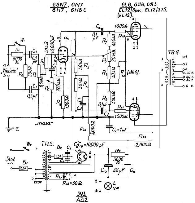
Fig. 1.
The voltages received from the spool of the potentiometer P1 are sent to the control grid of the first triode of the tube (6SN7) through the resistor Rs = 50,000 ohms (50K), which is a eliminator for possible parasitic currents. This grid is also connected to the 10.000 pF capacitor, which is connected via P2 = 100K potentiometer to the grounded base of the device ("ground"). This potentiometer is used to adjust the "timbre" of the amplified programs.
Radioamator (Radioamateur) 1950/09
- Details
- Category: Radioamator
- Hits: 7639

Radio amateur, September 1950, year I, number 9, price PLN 60.
CONTENT (1 cover page)
- Interference with radio reception.
- Let's learn radio technique.
- It's not difficult at all.
- Home loudspeaker installations.
- Radio probe.
- Diagrams of radio receivers T813.W and T813.GW.
- Rationalizer corner.
- Radio communications in the USSR.
- Radio engineering vocabulary.
- Editors' replies.
Diagrams of radio receivers types T813.W and T813.GW (cover page 2)
The presented diagrams show two popular radio receivers type T813.W and T813.GW.
The first of them, T813W type, is powered by alternating current, and the second - T813GW - by alternating or direct current from the lighting network. Receiving parts of radio receivers are assembled according to the same diagram. These are "simple", three-range, single-circuit receivers.
The T813W receiver has an AF7 electron tube, which acts as a detector, and an AL4 radio speaker tube.

Radio receiver type T813.W.
In the T813GW receiver the detector tube is VF7 and the speaker tube is VL4.

Radio receiver type T813.GW.
Both receivers use the same rectifying electron tube - AZ1. Both receivers have sockets for connecting a turntable, apart from the type, the T813W device has a switch that allows to reduce power consumption from the lighting network when listening to a strong local station.
Likewise, both receivers have permanent eliminators to eliminate interference in reception caused by the strong local station program. The setting of the waveband switches is adapted to receiving long waves.
The presented diagrams also show the voltages and currents (for both types of power supply) that should be in the individual circuits of the receiver. Knowledge of these values should facilitate the repair of the receiver.
The diagram of the radio receiver T813GW shows the connections of contacts on the board of the network switch for easier orientation during its repair.
Peace will win the war (1)
"The struggle for lasting peace, for the victory of fraternal coexistence among nations - is the most important task of the present generation. No one should doubt the final victory of this struggle, because the peace movement has become a movement of hundreds of millions of people today, and the ranks of active peace defenders are growing steadily. Nothing can stop the growth of this movement, because it is a movement for truth and justice in human relations. The strength of this movement is also based on the ever-increasing strength of nations liberated from capitalist violence, led by the mighty Soviet Union, led by the great peace standard-bearer Generalissimo Joseph Stalin. The Polish nation joins this fight for peace completely and with an unchanging will to win".
In these words delivered on September 2 this year to the delegation of the First Polish Congress of Peace Defenders - Bolesław Bierut, the President of the People's Republic of Poland, included the content of the struggle for peace waged today by the whole world. This was also the content of the session of the Warsaw Congress.
Interference with radio reception (2)
Industrial disruptions.
Contrary to atmospheric disturbances, the influence of which on radio reception is so strong that it often forces the device to be turned off and which almost cannot be avoided (see No. 6 of the magazine) - industrial disturbances can be effectively eliminated and can only be forced to abandon radio reception.
Interferences of this type are local in nature and come from electrical devices such as: AC and DC motors, vacuum cleaners, medical and hairdressing appliances, circuit breakers, etc. They most often manifest themselves in the form of tiring ear growling. Produced by the aforementioned devices - parasitic waves disrupting radio reception, they are most severe in large cities, industrial and health centers, where they create a "thick fog" which must be penetrated by radio waves sent into space by antennas of transmitting radio stations.
Let's learn radio engineering (5)
Cathode of electron tubes.
The basic electrode in any vacuum tube is the cathode. In order for the cathode to emit electrons, it must be heated to a relatively high temperature - several hundred or even over a thousand degrees. The cathode is heated with an electric, direct or alternating current. We have learned about two types of cathodes, namely direct heated cathodes and indirectly heated cathodes.
Direct-heated cathodes are usually made of tungsten wire, which in the case of small receiver tubes is usually activated by a track or bar, i.e. has an active layer of thorium or a layer of barium oxide on its surface in order to increase the emission efficiency of the cathode. The cathode wire on small receiver tubes is extremely thin. Its diameter is 10 microns, or 0.01 mm, while with high-power transmitting tubes whose emission reaches the value of 100 and more Amps, the diameter of the cathode fiber may be several millimeters..
...
Filaments for filing direct-glow electron tubes must be carefully suspended in the tube, and the finer the thinner the wire is. Usually, the cathode wire is suspended in one plane and it is in the shape of the letter "M" or the letter "V" inverted. The wire is suspended on springs, which is why it is subjected to a certain tension. This tension guarantees the suspension of the cathode in one plane and prevents the lateral warping of the wire during its heating due to thermal elongation of the wire. This ensures a constant distance between the wire and the anode or other electrodes in the tube (Fig. 1a and Fig. 1b).

Fig.1.
Fig.1a gives an example of a battery tube cathode suspension with a low filament current, i.e. having a very thin wire, while Fig.1b refers to a direct-glow rectifying tube in which a nickel tape covered with an active oxide layer is used. Such a tube generally has a relatively high emission. Pure tungsten wires without an active layer are not used in currently manufactured types of receiver tubes.
...
Indirect-heated cathodes.
Universal 15VA HI-FI amplifier
- Details
- Category: Radioamator
- Hits: 8477
Universal 15VA HI-FI amplifier.
Radioamator, Rok X, kwiecień 1960, Nr 4 (Radioamateur, Year X, April 1960, No. 4)
Editorial office: The following description concerns a system, the model of which was built at our request and practically tested by the designer.
The amplifier described here is perfect as a final power amplifier for playing music from records or tapes in the apartment. It is also suitable for broadcasting dance music in medium-sized halls and clubs.
Construction is easy; it can be performed by any radioamateur with basic theoretical and practical knowledge.
Output stage.
Due to the need to obtain a power equal to at least 10VA with very low nonlinear distortions, I decided to use the output stage amplifier in a push-pull configuration with negative feedback. This is called "ultralinear" system. The feedback voltage in this system is obtained from taps, or from separate windings on the output transformer. By changing the ratio of the alternating voltage of the screen grid to the anode alternating voltage, we change the working conditions of the end tubes. With this ratio equal to one, the tubes work as triodes, because the shielding grids are connected with the anodes, while with the ratio equal to zero, they act as pentodes (Fig. 1).

Fig. 1. "Ultralinear" system.
For the ratios with intermediate values, the circuit has a number of advantages over push-pull circuits, both with triodes and pentodes, and above all, less nonlinear distortions at large and small signals, at the cost of low power loss. Moreover, such feedback significantly reduces the internal resistance of the system.
For EL34 tubes, the 20% tap is the most advantageous (Usz / Ua = 0.2, of course, from the power supply side).
The "ultralinear" circuit with EL84 tubes gives about twice less nonlinear distortions compared to the conventional push-pull circuit with 10% lower power. The "ultralinear" circuit requires a special design of the output transformer.
Output transformer.
Both halves of the anode windings of the transformer should be placed symmetrically by dividing the window into two sections, each for one half of the anode winding. The unbalance has a significant impact on the phase shifts and amplitude differences between the anode current and the screen voltage, so that even harmonics of higher frequencies may not reduce each other.
Fig. 2 shows a diagram of the windings of such a transformer, and Fig. 3 shows the arrangement of the windings.
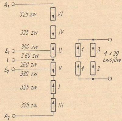
Fig. 2. Diagram of the windings of the output transformer.
Primary windings: 0.18mm copper wire in enamel.
Secondary windings: 0.75mm copper wire in enamel.
Portable universal amplifier
- Details
- Category: Radioamator
- Hits: 8508
Portable universal amplifier.
Radioamator, Rok X, wrzesień 1960, Nr 9 (Radioamateur, Year X, September 1960, No.)
This description concerns the model awarded with the consolation prize in the Great Radio Amateur Model Contest.

From the editorial office:
The amplifier described below is an example of a well-thought-out design for a specific purpose. A simple but full-fledged system, proper use of power thanks to the use of efficient domestic speakers, good adaptability to portability, cheap and effective finish - these are the main features of the device. We can recommend the construction of this device to anyone who wants to have a good portable amplifier for playing recordings from discs, enhancing solo performances and increasing the acoustic power of the receiver when using dance music..
The AMPLIFIER was designed and made for a stage singer producing with an electric guitar. On this assumption, the device should meet the following conditions:
- small dimensions and weight,
- high quality playback,
- high (10W) output power,
- easy to carry and easy to use.
It would be very difficult to meet the above conditions to the full extent, therefore a compromise solution was necessarily applied in the model made. First of all, a system with a mains transformer was adopted (Fig. 1), although in the universal version the weight of the apparatus would be absolutely lower.

Fig. 1. Schematic diagram of the amplifier.
Nevertheless, it was found necessary to galvanically separate the amplifier, microphone and guitar circuits from the network. In contrast, the reduction in dimensions and weight was achieved by a different route. The output power of the amplifier was limited to 5W, filling its final stage with a single EL84 pentode. The reduced output power, in turn, was used as rationally as possible, feeding two lightweight speaker sets with relatively high efficiency.
New types of tubes for push-pull and stereo amplifiers
- Details
- Category: Radioamator i Krótkofalowiec
- Hits: 9499
New types of tubes for push-pull and stereo amplifiers.
Radioamator i Krótkofalowiec, Rok XI, Marzec 1961, Nr 3
Among the many new types of receiver tubes that have recently been introduced to the market by Western European manufacturers, the ELL80 and PLL80 dual speaker pentodes deserve special attention. The idea of placing two tube systems in one bulb has been known since the birth of the now obsolete ECL11 tube, which at the time was a kind of revelation; it was followed by further, more modern types, such as ECL82 ... 86 and their equivalents in the U and P series. Placing two end pentodes in one balloon is, however, something completely new, resulting from the current needs of the electronics industry, in particular from the needs of modern stereo technology.
The final stages of the stereo amplifiers were initially filled with the standard ECC83 + 2xEL84 set, consisting of a total of three tubes. The use of ECL82 tubes made it possible to reduce the number of tubes to two, and - with the same number of stages - had an impact on the cost of the device. However, equipping the same circuit with the ECC83 - ELL80 set is more rational at the same cost, as it allows for a favorable and transparent assembly, allowing you to easily avoid undesirable microphonics, various types of couplings, etc. As you know, two stages with a very strong overall amplification (in the case of an ECL tube) is quite critical and requires careful elaboration of both electrical and mechanical systems in terms of the stability of the system. The popular ECL11 tube was particularly capricious in this respect.
 Fig. 1. Schematic diagram of the 2 x 3W amplifier with ECC83 and ELL80 tubes and its technical parameters.
Fig. 2. Schematic diagram of the 2 x 2.6W amplifier with ECC83 and PLL80 tubes and its technical parameters.
.
Fig. 3. Schematic diagram of the push-pull amplifier with ECC83 and ELL80 tubes and its technical parameters.
Read more: New types of tubes for push-pull and stereo amplifiers
Design of output transformers
- Details
- Category: Radioamator i Krótkofalowiec
- Hits: 13910
DESIGN OF OUTPUT TRANSFORMERS
Radio amateur and amateur radio operator of Poland, Year 24, December 1974, No. 12.
Low-frequency tube amplifiers, especially with higher power, are still built by radio amateurs. The output transformer is the most difficult element to design and manufacture. This is evidenced by inquiries and requests for help in the calculations sent to the editorial office. The basic principles of designing transformers intended to be made in amateur conditions presented here briefly should satisfy the wishes of interested readers.
The principles of designing low-frequency transformers in amateur conditions are slightly different from those used in industry. First of all, it is determined approximately what core is needed for the designed amplifier. Then a more or less suitable core is searched for, and after it is acquired, further winding calculations are made. After establishing approximate data as to the necessary winding wires, wires with diameters similar to the selected ones are purchased and only then the number of turns of individual windings is finally determined.
The basic relationships linking the phenomena in a transformer result from the following formula:
Etr = 6,28⋅f⋅n⋅Q⋅B⋅10-4 (1)
where:
- Etr - the amplitude of the reverse-electromotive force induced in the primary winding, approximately equal to the amplitude of the supplied voltage [V],
- f - frequency [Hz],
- Q - core cross-section [cm2],
- n - number of turns of the winding,
- B - the highest induction value in the core [T].
The value of the reverse electromotive force is related to the alternating voltage of the final amplifier stage and results from the power and operating resistance. The highest and the lowest frequency of the passband results from the assumptions. The highest allowable induction value in the core should not exceed 0.6T. For Hi-Fi amplifier transformers, it is recommended to take 0.4T. Two unknowns remained in the formula given: the core cross-section (Q) and the number of turns (n). We determine the core cross-section approximately from the formula:

where:
- Pwy - the output power of the amplifier.
As far as possible, we aim to build a transformer with a large core cross-section, which will allow to reduce the number of turns in the windings. This is important both due to the undesirable leakage inductance of the transformer and the degree of difficulty of its manufacture. In transformers composed of sheets with holes for fastening bolts, it is necessary to check that the core cross-section near the bolts is not smaller than that of the main column.
The simplified transformer substitute circuits are shown in Fig. 1. At the lowest frequency, the influence of the inductance of the transformer primary winding, which is connected in parallel to the appropriate amplifier load, should be taken into account. In most cases, it is the necessity to obtain a sufficiently large value of this inductance that determines the number of turns of the primary winding. At medium frequencies (1000Hz is assumed), only the winding resistances play an important role. At high frequencies, the influence of the leakage inductance is noticeable, the value of which depends on the number of turns, the transformer winding scheme and its quality. This inductance, in combination with the inter-winding capacitances, creates a low-pass filter limiting the transformer bandwidth..

Fig. 1. Simplified equivalent transformer diagrams.
a - equivalent circuit for the lowest frequencies,
b - equivalent circuit for medium frequencies,
c - equivalent circuit for great frequencies (treble and ultrasound).
Class D transistor amplifiers
- Details
- Category: Radioamator i Krótkofalowiec
- Hits: 9380
Class D transistor amplifiers
Radio amateur and short wave amateur 1971/03
Wojciech Czerwiński
Jerzy Kwaśniewski
Pulse circuits with transistors switched from cut-off to saturation have found wide application in digital and automatic control technology, among others due to their high efficiency. The search for a way to increase the efficiency of transistor acoustic amplifiers has led to an application for amplifying low frequency signals switching amplifiers working in class D. Such amplifiers show efficiency of 90%, unattainable in conventional systems of class A, B or C.
Principle of operation
Let us briefly consider the principle of amplifying harmonic signals in pulse amplifiers. Class D work is a type of amplifying element operation in which the element in the working cycle is only in two states: complete blocking when no current flows through it, or complete unblocking when the voltage drop on it is close to zero. If a current flows through the resistor in the form of rectangular pulses shown in Figure 1, then the average value of the current Io marked with a dashed line may be equal to zero (Figure 1a), greater than zero (Figure 1b) or less than zero (Figure 1c) . The ratio of the pulse duration to the repetition period is called the duty cycle γ.
For the waveforms in Figure 1, the γ factor is respectively: γ = 0.5, γ> 0.5 and γ <0.5. If the change of γ from the maximum to the minimum value is carried out according to the function e.g. sin (ωt), then in such a series of pulses the average value of the pulses will be the low frequency harmonic component sin (ωt).
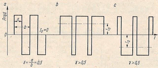
Fig. 1. Rectangular waveforms with different fill factors.
Otherwise, the stage operating in the impulse system can amplify the low frequency vibrations, if we apply a pulse train in which the positive half-period of the low frequency signal is the pulses with the value of γ> 0.5 correspond to the negative half-period, and the pulses with the value of γ <0.5 correspond to the negative half-period (Fig. 2). We are dealing here with pulse width modulation. It goes without saying that the pulse repetition frequency should be much greater than the highest frequency of the amplified low frequency waveform.
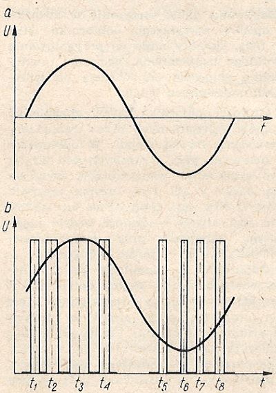
Fig. 2. Pulse width modulation with a sine wave>
a - modulating waveform, b - impulse modulated waveform.
Pulse width modulation can be implemented by various methods. The simplest way is shown in Fig. 3. The triangular voltage is compared with the sinusoidal voltage representing the low frequency signal. Square-shaped pulses appear at the modulator output, the length of which depends on the amplitude of the amplified signal. The triangle waveform can be obtained from square pulses using a Miller integrator.
Radioelektronik (Radioelectronics) 1990/12
- Details
- Category: Radioelektronik
- Hits: 12402
Radioelectronics, December 1990, volume XLI (139)
FROM THE COUNTRY AND FROM THE WORLD (cover page 2)
- PHILIPS FSB260 and FSB290 hi-fi sets.
These new, uniform-looking audio sets (photo shown on cover) are intended for a wide range of middle-income buyers. Both types of sets are equipped with remote control systems, have identical turntables and CDs, but some differences exist in other parts of the sets. - Handy, amateur mixer - tape recorder.
The Japanese company Fostex offers a new mixer - X-15-II cassette deck. The device has external dimensions of 75 x 290 x 195 mm (with a plug-in battery: 75 x 290 x 195 mm) and a weight of 2.9 kg (with battery). A standard C-60 or C-90 cassette is used to make a 4-track recording from the four inputs of the device. - The easiest installation of optical fibers.
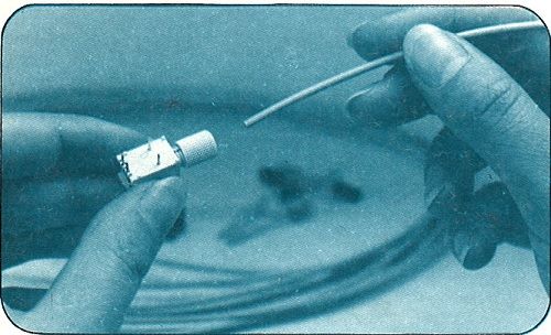
Early in the development of fiber optics, installing fiber optics was something of a "higher school of gas cooking" - potentially simple, but required special tools and staff preparation. Today, when installing fiber optics in the home and in the car, it had to be kept to a minimum. This is the purpose of the twisted fiber optic connector.
- Telephones for the cellular network.
The cellular telephone network in developed countries has been a reality for several years, there is also hope that as a result of giving up the state monopoly, it will appear in our country, at least in the largest urban agglomerations. - Cooperation in microprocessors.
Two European "greats" - Siemens and SGS-Thomson - cooperate in the development, production and sale of 8 and 16 - bit microprocessors. The family of 16-bit microprocessors developed by Siemens is already beginning to appear on the market (the first commercial chip is the 80C116) and, as it turned out, it surpasses everything that was previously available in this class of chips..
ANNOUNCEMENTS (1)
ELECTROACOUSTICS - "Duetto-Stereolith" SPEAKER SYSTEM (2)
The company REVOX, known for its high quality products, offers a stereo loudspeaker system operating in accordance with a new concept. As it is easy to reproduce and gives interesting sound effects, it is worth getting to know it better.
The classic way of stereo reproduction requires the use of two loudspeakers separated by a distance, the so-called base. The optimal stereo listening position is in front of the loudspeakers, symmetrically to them. It has long been noticed that when using loudspeakers with a wide angle of sound or omnidirectional radiating units, the position of the listener in relation to the loudspeakers is less critical, but the stereo image of the sound becomes less accurate, especially in terms of the location of the apparent sound sources.
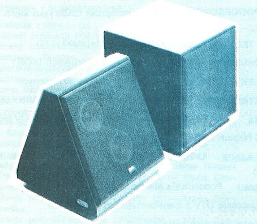
The Swiss acoustician - Walter Schupbach - proposed a solution consisting in placing the speakers of both channels in one housing in such a way that they radiate in opposite directions, i.e. to the left and to the right of the listener. It turned out that the best results are achieved by a housing with a triangular cross-section (see the drawing), divided by a wall into two parts. This solution can be compared to the radiation of sounds by one source, in principle omnidirectional, but the sounds radiated to the left and right and their reflections differ due to the fact that they correspond to different stereo channels.
DISTORTIONS CAUSED BY ELECTROLYTIC CAPACITORS (2)
When designing electronic circuits, capacitors are considered linear elements. This does not correspond to reality, especially in the case of electrolytic capacitors, which under certain conditions may cause nonlinear distortions. This is the subject of this article.
We know that the capacitance of electrolytic capacitors varies significantly with temperature changes (it decreases rapidly at subzero temperatures) depending on the frequency of the alternating current. The capacity of a good, fully functional and formed electrolytic capacitor changes slightly depending on the value of the DC bias voltage, as shown in the figure.
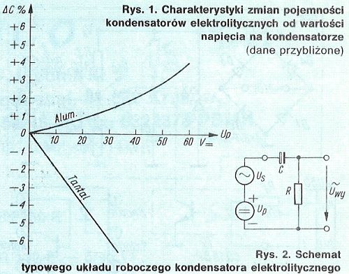
It follows that in the case of electrolytic aluminum capacitors there is an increase in capacitance with an increase in the polarizing voltage, and in the case of tantalum capacitors - on the contrary, there is a decrease in capacitance.
Radio engineering time travel - 1930
- Details
- Category: Radio USA
- Hits: 17901

Radio engineering time travel (1930)
I invite you to look at the "pictures" related to radio technology in 1930. They come from various sources. The gallery has its sister version in Polish and Russian. Versions in other languages will be added successively. More detailed descriptions can be found in other language versions (articles are related and can be displayed by clicking on the icons with flags on the left, top of the TRIODA website). Of course, I will complement translations of signatures quite slowly. All descriptions are displayed using the present tense and not the past - this is not a mistake only deliberate action - a reference to the original descriptions from those years. In order not to delay the possibility of viewing the gallery, this site is made available as a "site under construction" - for which I apologize to all guests. At the beginning and end of each set of photographs there are links allowing to change the period - calendar year.
Radio engineering time travel
- Details
- Category: Radio USA
- Hits: 20478
Radio engineering time travel (to 1921)
I invite you to look at the "pictures" related to radio technology. They come from various sources. The gallery has its sister version in Polish and Russian. Versions in other languages will be added successively. More detailed descriptions can be found in other language versions (articles are related and can be displayed by clicking on the icons with flags on the left, top of the TRIODA website). Of course, I will complement translations of signatures quite slowly. All descriptions are displayed using the present tense and not the past - this is not a mistake only deliberate action - a reference to the original descriptions from those years. In order not to delay the possibility of viewing the gallery, this site is made available as a "site under construction" - for which I apologize to all guests. At the beginning and end of each set of photographs there are links allowing to change the period - calendar year.
Page 6 of 10
Select your language
")
")
")
")
")