Home
How an Output Transformer Causes Distortion Part 1
- Details
- Category: Audio USA
- Hits: 9998

How an Output Transformer Causes Distortion
In Two Parts - Part 1
Audio, February, 1957, Vol. 41, No. 2 (Successor to RADIO, Est. 1917).
Norman H. Crowhurst
The operation of audio transformers has long been surrounded with an aura of mystery. This article distinguishes the different forms of distortion an output transformer can produce, and gives some simple measurement methods.
The use of audio transformers has long been depreciated on the grounds that they cause distortion. In fact the output transformer seems to be almost the sole survivor of the species and many attempts have been made to do without even this. A few amplifiers have been designed to dispense with the output transformer, apparently in the belief that the output transformer is the principal remaining cause of distortion.
Careful analysis will usually show that the tubes introduce more distortion than the output transformer would have and that that a well-designed amplifier using the conventional output transformer can achieve a much lower order of distortion than is possible without one.
A few simple facts about transformers seem to get overlooked: when the tube curvature causes distortion it distorts all frequencies; but the distortion a transformer causes due to nonlinearity of its magnetizing current is concentrated at the low-frequency end. The worst transformer made will not distort the middle frequencies and the way it distorts at both lower and higher frequencies is one of the things we shall clarify in this article.
But, surely, someone will say, a transformer can cause distortion at middle frequencies? "I remember replacing a transformer, and the replacement would not give so much power without distortion as the original did." Doesn't this prove that the transformer distorts at the middle frequency? To understand the cause of this experience, let's consider the effect of transformer efficiency on amplifier performance.
The Importance of Efficiency
Amplifiers are rated to give a certain maximum output, determined by the performance of the output tubes. However, the output power is always measured on the secondary side of the output transformer, as shown at Fig. 1.

Fig. 1. Usual method of measuring output power consists of calculating the watts dissipated in a load resistor connected to the secondary of the output transformer. While this is the available power output, the output tubes actually deliver a little more than this.
A good output transformer is probably about 95 per cent efficient. This means that, if the amplifier gives 50 watts output, measured on the secondary side of the transformer, there must be nearly 53 watts output delivered to the primary side from the output tubes. The output tubes are having to give nearly 53 watts output for us to measure a good 50 watts.
Read more: How an Output Transformer Causes Distortion Part 1
Two-stage mains powered amplifier
- Details
- Category: Radioamator i Krótkofalowiec
- Hits: 6495
Two-stage mains powered amplifier
Radioamator i Krótkofalowiec 1961/11. Author: K.W.
(A corner for beginner radio amateurs)
The simple one- and two-stage battery amplifiers described in the previous issues of the magazine helped us to get acquainted with the basic circuits of this type of amplifiers. We must say, however, that battery power, apart from its specific advantages, has a major disadvantage: it is uneconomical. Therefore, wherever possible, radio equipment is powered from AC power circuits.
AC powered amplifiers, popularly known as "mains" amplifiers, differ from battery amplifiers in that, apart from the actual amplifying circuit, they are equipped with a power module, usually composed of a mains transformer, a rectifier tube and a rectified voltage smoothing filter. Some details about the layout and operation of the power supply were given in the previous issue when discussing the design of the power supply, intended for cooperation with a two-stage low-frequency amplifier. The power supply is usually constructed as one unit with the amplifier or receiver system (e.g. radio receivers), and only in special cases it constitutes a separate element. The latter solution is used, for example, in the popular tourist receiver "Szarotka".
There is also a second, fundamental difference between a mains and a battery amplifier: the use of other types of tubes. This issue requires further discussion due to its crucial importance.
As we remember from the short explanation of the principle of operation of the electron tube ("Radioamator" No. 5/61), the cathode is the source of electron emission inside it. In the case of battery-operated tubes, it is simply a thin filament, heated to an appropriate temperature. The design of the cathode of the vacuum tube adapted to AC power is more complex.
Figure 1 shows us in cross-section the cathode of such a modern vacuum tube. It is an "indirectly heated" cathode. As we can see, it consists of two basic elements: an electric heater made in the form of a spiral of resistance wire and the actual cathode. The latter, usually made in the form of a ceramic tube, is covered on the outside with a suitable substance which, when heated to an appropriate temperature, emits electrons. As you can see, the filament circuit does not directly participate in the work of the amplification circuit.

Fig. 1. Cathode of an indirectly heated electron tube (cross-section)
Indeed, the fragment of the amplifier diagram with the tube in question shown in Fig. 2 has a filament circuit completely independent of the rest of the circuit.
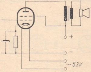
Fig. 2. Part of the schematic diagram of an amplifier with an indirectly heated electron tube
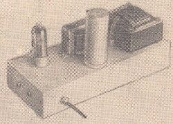
Now we can present our readers a schematic diagram of one of the mains amplifiers. As shown in Figure 3, it is a simple and economical system, as it uses only one modern ECL82 electron tube.
Stereo amplifier
- Details
- Category: Młody Technik
- Hits: 7070

Stereo amplifier
Młody Technik 1972/09 (Young Technician 1972/09)
MSc. Franciszek Lesiak
The amateur construction of a high-quality stereo amplifier is very difficult and requires a lot of theoretical knowledge, practical skills, as well as considerable financial resources. Therefore, we offer those who are interested in making a simplified high-quality amplifier, not necessarily HI-FI, but with better parameters than the amplifiers described so far in the "Young Technician" magazine.
The device is characterized by a significant output power sufficient to amplify a large room, e.g. a common room, club, etc., a wide band of transmitted frequencies and a low coefficient of non-linear distortions.
The audio set consists of an amplifier and two loudspeakers. Basic data of the amplifier:
- 2 x 10 W output power with a distortion of 1.5%,
- Frequency response 30 ÷ 15,000 Hz,
- Sensitivity 0.2V,
- Tone adjustment:
- ± 10 dB at 50 Hz,
- ± 10 dB at 10 kHz,
- Dimensions 440 × 230 × 110 mm.
The schematic diagram of the amplifier is shown in Fig. 1. Each channel of the system contains a three-stage power amplifier in a push-pull circuit built on EL84 tubes, and also a gain and tone control system.
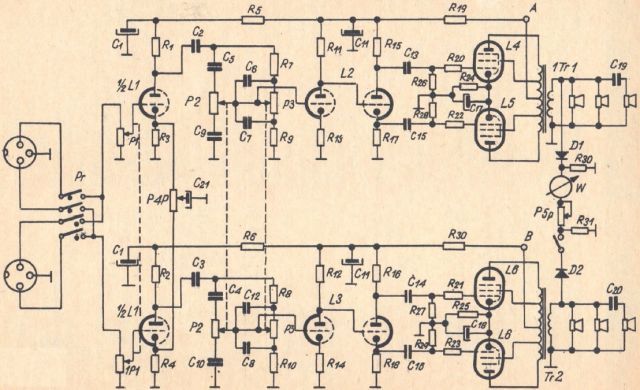
Fig. 1. Schematic diagram of the amplifier
The input signal from one of the two input sockets goes through a switch Pr to the potentiometer P1 used to adjust the volume, and then to the grid of the tube L1, which is the first stage of voltage amplification. Both cathodes of the tube L1 are connected to the leads of the potentiometer P4, the slider of which connects to the capacitor C21.
Assembling the simplest low-frequency tube amplifier (II)
- Details
- Category: Radioamator i Krótkofalowiec
- Hits: 7448

Assembling the simplest low-frequency tube amplifier (II)
Radioamator i Krótkofalowiec 1961/06. Author: K.W.
(A corner for beginner radio amateurs)
The previous issue of the magazine gave novice radio amateurs a description of the operation and construction of a tube amplifier with a very simple design with an input transformer. At the same time, a diagram of a similar circuit equipped with a potentiometer for volume control was presented. Now, as announced, we will discuss the amplifier layout in this modified version, with assembly instructions and drawings as usual. Undoubtedly, they will facilitate the correct construction of this simple amplifier.
The operation of the amplifier, the diagram of which is shown in Fig. 1, is of course analogous to the operation of the previously discussed circuit, and we refer to it all Readers interested in its construction.
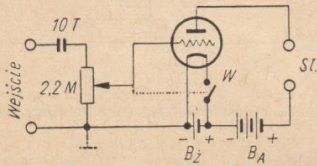
Fig. 1. Schematic diagram of the amplifier
The input circuit of the system requires a separate discussion, not only because it is still unknown to us, but above all because of its great popularity. As we know, each radio receiver or amplifier is equipped with a knob with which you can adjust the volume of the received broadcast or playback. This knob is nothing more than a component part of an element called a potentiometer.
Read more: Assembling the simplest low-frequency tube amplifier (II)
Assembling the simplest low-frequency tube amplifier (I)
- Details
- Category: Radioamator i Krótkofalowiec
- Hits: 9261

Assembling the simplest low-frequency tube amplifier (I)
Radioamator i Krótkofalowiec 1961/05. Author: K.W.
(A corner for beginner radio amateurs)
Despite the constant progress in the production and application of semiconductor elements such as diodes and transistors, the electron tube is still an essential component of most radio engineering devices. As we know, the electron tube, invented about fifty years ago, created great development prospects for radio engineering and became the basis of its extraordinary career. The knowledge of the construction and principles of operation of the vacuum tube is the first step of "initiation" of each radio technician and therefore it is also valid for beginner radio amateurs. We will establish our knowledge of electron tubes in the simplest way, i.e. by hand-assembling and testing a single-tube low-frequency amplifier. This amplifier can be used as a detector receiver and be - despite its simplicity - very useful, for example, if you need to listen to a broadcast using a larger number of headphones (2 - 6 pairs).
The schematic diagram of the amplifier is presented in Fig. 1 in two variants, which differ in the way of feeding the signal from the detector to the amplifier circuit. In the first case (Fig. 1a), a low-frequency coupling transformer with an appropriately selected ratio is used. This system should be used when the signal obtained from the detector receiver is very weak, and we want to obtain the highest possible gain. No volume (gain) control is provided here. The use of the amplifier in the circuit shown in Fig. 1b is, however, advisable when the receiver plays programs at a relatively high volume; this amplifier is slightly simpler in design, and at the same time allows you to adjust the volume. However, we must remember that the gain provided by this system is lower than the maximum one provided by the same electron tube coupled to the detector by means of a transformer. Of course, in both cases the acoustic signal from the output of the detector receiver is connected to the same electrode, the so-called the "control grid" of the vacuum tube.
Read more: Assembling the simplest low-frequency tube amplifier (I)
High-quality 2x10W stereo reproduction set
- Details
- Category: Radioamator i Krótkofalowiec
- Hits: 7013
High-quality 2x10W stereo reproduction set
Michał Gołębiowski, Radioamator i Krótkofalowiec 1970/05
(The description concerns a model made in cooperation with the editorial office of the magazine and practically tested by the designer)
Despite the rapid progress of transistor technology, electroacoustic devices equipped with electron tubes are still quite often made by radio amateurs. This is justified due to the still high cost of semiconductor elements and the fact that starting transistor devices is generally more difficult and troublesome than their tube counterparts and requires good knowledge of the issue and extensive practical experience.
This description is addressed to radio amateurs who already have some achievements in the construction of electroacoustic devices and would like to obtain a higher quality reproduction set at a relatively cheap cost.
Technical data of the stereo amplifier
- Maximum output power with non-linear distortions in the band 40Hz ÷ 16000Hz and Rload = 7.5Ω less than 1% (sinusoidal signal): 2x10W.
- Frequency characteristics (1.5dB band): 30Hz ÷ 20000Hz.
- Sound tone adjustment in relation to the frequency of 100Hz:
at 60Hz: + 6dB ÷ -12dB
at 12kHz: + 6dB ÷ -15dB - Crosstalk attenuation between the channels in the 30 ÷ 16000Hz band: ≥ 40dB.
- Stereo balance control: ± 6dB.
- Input resistance:
"magnetic adapter" input - 100kΩ
"crystal adapter" input - 100kΩ
"microphone" input - 80kΩ
"radio" input - 1MΩ
"additional" input - 0,5MΩ. - Input voltage for maximum output power at f = 1000Hz and Rload = 7.5Ω:
"magnetic adapter" input - 5mV
"crystal adapter" input - 70mV
"microphone" input - 4mV
"radio" input - 330mV
"additional" input - 150mV. - Signal-to-noise ratio at maximum output power: ≥50dB.
- Change in output voltage when the load is disconnected: ≤1dB.
- Mains power: 220V, 50Hz, maximum power consumption 55W.
- The remaining parameters are presented in the form of appropriate characteristics in Figures 5, 6, 7, 8 and 9.
About the durability of electron tubes
- Details
- Category: Radioamator i Krótkofalowiec
- Hits: 7627
About the durability of electron tubes
(Radioamator i Krótkofalowiec 1970/02)
Currently, over three million TV sets are registered in Poland. These are almost exclusively receivers based on electron tubes and it can be assumed that in the near future the electron tubes will not be completely replaced by transistors. Taking an average of 15 electron tubes in one TV set and adding to them electron tubes operating in radio receivers and tape recorders, you will get approximately 70 million electron tubes systematically used in these devices. Due to their huge number, the "life" time of the electron tube is interesting. The factories usually guarantee the operation time of this type of electron tubes from one thousand to several thousand hours. This does not mean, of course, that an electron tube (operated in proper conditions) cannot "end" before this time elapses, or work for a much larger number of hours.
Triode Loadline Simulator
- Details
- Category: Tools
- Hits: 23077

The program allows to determine the optimal operating point of a triode. It does not require installation and can be run by most web browsers. This is the first version of the program, which will be extended with new opportunities.
Using the program is intuitive. Just click at the following link:
RUN
Here is the screenshot of the simulator window.
To change the parameters use triangular indicators that can be dragged using the mouse. There are six indicators, numbered from 1 to 6.
Tube amplifier "Concertino"
- Details
- Category: Photo gallery
- Hits: 8765
Photos and description - Marcin Sławicz
The beginnings of the project
The idea of building my own tube amplifier has been bothering me for the last two years. I am not a maniacal audiophile and using "ordinary" solid state equipment was enough for me (I always preferred to listen to music than equipment). Now, however, my worn-out amplifier is starting to suffer from the ailments of old age, and although I could regenerate it, there is a great opportunity to implement a tube venture.
At the beginning I was thinking about a design based only on triodes, but rejecting the SE circuits burdened with too many inconveniences. A very interesting description of the push-pull amplifier with direct filament triodes can be found on the Lynn Olson website. It is worth taking a look there because of the extremely interesting solutions used in his projects. The described amplifiers, however, have a major disadvantage - cost (mainly due to the 300B or 2A3 tubes and interstage transformers). So I had to look further.
My attention was drawn to indirectly heated double 6AS7 power triodes, once used mainly in power supply systems, but also great as electron tubes in the output stage of audio amplifiers. The cost of electron tubes would be much lower, but due to the low voltage gain factor, in this case, expensive and difficult to obtain interstage transformers or two or more triodes in parallel connection would have to be used. Mr. Russ Sadd described on his website a push-pull amplifier with 6AS7 triodes.
My project took a few more months, during which I slowly became convinced that a successful power amplifier does not have to have triodes in the output stage. I began to consider the use of beam tetrodes working in the gain stage in an ultra-linear configuration. Such a circuit combines the advantages of triode sound (low distortion) with high efficiency and stability of tetrodes and pentodes. I had a choice of 6L6 / 5881, KT66, KT88 / 6550 tubes, commonly used both in guitar amplifiers and in Hi-Fi designs.
Another period of my project is searching the net in order to select the basic amplifier circuit. The amplifier should not be complicated, because a complex circuit does not guarantee high-quality sound, and with limited measurement possibilities, it can be difficult to start up. Mass-produced devices must ensure the repeatability of production and the relative stability of parameters during subsequent operation. When designing an amplifier for yourself, you can often take shortcuts without worrying about the subsequent service.
My choice fell on a well-known layout that has been tested in thousands of homes around the world. It will be the next version of the D.T. N. Williamson. Almost every company that used to produce tube amplifiers had a product to a greater or lesser extent based on this famous circuit. You can find hundreds of articles on the Internet describing different varieties of Williamson amplifiers. So let's take advantage of these rich experiences today.
Design assumptions
In 1947, Mr. Williamson introduced an amplifier circuit that was a real breakthrough in the pursuit of high-quality sound reproduction. The most characteristic elements of this amplifier are the split load phase splitter and the use of a transformer transmitting the signal in the range of 2Hz ÷ 60,000Hz (a necessary condition for achieving the stability of the amplifier with a closed feedback loop).
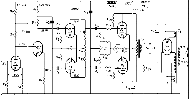
All stages of the Williamson amplifier are, in fact, extremely simple, but at the same time they perfectly cooperate with each other, ensuring relatively low signal distortion. Nevertheless, the system has several drawbacks, which efforts were made to improve in the following years. The figure below shows the 1949 version of the amplifier with the component values marked.
Radio "Латвия" (Riga) M 137
- Details
- Category: Photo gallery
- Hits: 6561

Grzegorz Makarewicz "gsmok"
The concept of the radio receiver was developed in 1947. Its mass production, however, began much later, in September 1950. In 1952 it underwent some modifications and was sold under the name "Mir M152". I have no idea what the modifications were. I have not found any reliable information on this. Some detailed information about the radio can be found on the page "M137". According to the content given there:
"One of the features of the Latvian" M 137 "radio receiver is the scale in which the crosshair is connected to the indicator of the range selector. In each of the 5 bands, a bright dot on a red background indicates the tuning frequency of only the selected band. In reception mode, the line goes out. Radio speaker - "10GDP-VEF" (10 W) with a 250mm diffuser. Among the creators of this radio was Gintauts Aboltins-Abolins, later a well-known constructor of the "Orbita" design office, and from 1968 the head of the Department of Electronic Equipment Design and Production Technology of the Radio Engineering Faculty of Riga University of Technology. In the newspaper "Vefietis" you can find articles about console radios based on the receiver "Латвия M137". One carries the inscription "To my dear commander, father and teacher Józef Vissarionovich Stalin on the 30th anniversary of the Komsomol - Komsomol members and youth of Riga." Another one was created on the occasion of the 10th anniversary of the USSR in July 1950."
The radio is really impressive. When I was in his possession, my reaction was clear.

Photo 1. I tried to whistle, of course, but my mouth was dry with admiration and my eyes went to different parts of the world.
I showed the radio to the cats, which usually hang around, and unfortunately was a bit disappointed. Their reaction was quite different. They did not even deign to get off the chair.

Photo 2. The cat at the top is "Cypis", the cat at the bottom is "Deedee". Cats are said to sleep 70% of their lives. "Cypis" sleeps at least 95%.
Let us return, however, to the subject of the description. Here is the radio in all its glory.

Photo. 3.
Basic parameters of the radio:
- Sensitivity: not less than 50 μV.
- Output power - 6W in the frequency range 60Hz ÷ 6500Hz.
- Power drawn from the mains: 190W.
- Supply voltage: 110V / 125V / 220V.
- Dimensions: 642mm / 406mm / 292mm.
- Weight: 30 kg (I found out about it turning the radio while taking the photos below).
Page 4 of 10
Select your language
")
")
")
")
")