
Output transformers - Part I and II
An easy-to-understand discussion of the factors that affect the performance of all output transformers.
Author: JAMES MOIR (Technical Director, Goodmans Industries, Ltd., Wembley, Middx., England).
AUDIO, FEBRUARY-MARCH, 1960, VOL. 44, No. 2-3 (Successor to RADIO, Est. 1917).
The output tubes in common use in audio amplifiers require anode loads of between about 1000 ohms and 10000 ohms if the maximum undistorted power output is to be obtained. There are practical difficulties in winding a loudspeaker voice coil with the large number of turns of fine wire required to achieve such high load impedances directly and thus it is common practice to insert an output transformer between a speaker of low impedance and the output valves as in Fig. 1 in order to "match" the speaker to the valves. The ensuing discussion is intended to be a simple explanation of this matching process and of all the factors that control the frequency response and the distortion introduced by an output transformer.
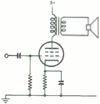
Fig. 1. Output transformer used to obtain the correct load impedance and isolate the voice -coil current from the plate supply.
Loudspeaker voice coils can be wound with sufficient turns to give an impedance of 3 ohms to 4000 ohms and, in fact, these were common in the very early days of radio.
However, the difficulties of winding make the cost almost prohibitive, and such a high percentage of the limited space available is occupied with insulation between turns that the efficiency is rather low. It need hardly be stressed that the use of high-resistance wire is an inadmissible solution to the problem for this merely increases the amount of audio power that is dissipated uselessly in heating the loudspeaker voice coil. The efficiency of loudspeakers is already too low for any further loss to be tolerated.
There are other difficulties in the way of connecting the voice coil directly in the anode circuit of a valve or valves. If used in this way the valve anode current must pass through the voice coil, increasing the amount of power that is dissipated in heating the coil and interacting with the magnetic field in the gap in such a way as to drive the coil out of the gap. This is a difficulty that is eased but not eliminated by the use of a pair of valves in push-pull as in Fig. 2, for while the anode current can be balanced out in the no-signal condition the balance does not hold at other signal levels, nor does it usually hold for more than a few minutes after the adjustment is made. If a transformer is not used the trouble can only be eliminated by inserting a large blocking capacitor though this would need to be of several thousand microfarads (for a 15-ohm loudspeaker) in order to maintain the response at low frequencies.
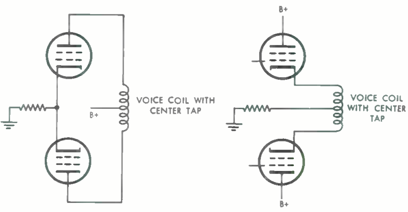
Fig. 2. Use of push -pull connection balances anode current but does not eliminate difficulties due to current in voice coil.
Both problems - that of removing the anode current from the coil while efficiently raising the voice coil impedance are solved by the use of an output transformer as in Fig. 1. This is the solution that is commonly adopted even though it involves the addition of another relatively expensive component. Iron cored transformers have a reputation as "distortion introducers" but later in the discussion it will be shown that when properly designed, an output transformer need be no worse than most of the other components in this respect. If the amplifier design is such that the output transformer can be inserted in the feedback loop, the extra distortion introduced is absolutely negligible by any standard.
Functioning of Transformer
First of all let us consider just how an output transformer enables a low-impedance loudspeaker to appear as a high-impedance load in the anode circuit of a valve. The basic transformer merely consists of two coils of wire wound around an iron path common to both coils as in Fig. 3. An alternating voltage applied to either pair of terminals results in a current flowing in the coil and the appearance of magnetic flux in the core. At any instant the flux may conventionally be thought of as emerging from the top of the coil, "flowing" around the iron circuit and re-entering the bottom of the same coil. One half cycle later the direction of flow of both current and flux will be reversed. It is important to note that all the flux produced by the current in one coil is guided through the second coil by the iron core.
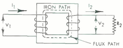
Fig. 3. Diagram of basic transformer.
At this point there emerges a phenomenon that is basic to all transformers; the flux produced by the voltage applied to can be minimized by working the transformer core at a low magnetic flux density.
Eddy-current losses are the second component of the iron loss and are found to be proportional to (flux density)2 and (frequency)2. Their origin is interesting. Very early in the present discussion it was noted that an E.M.F. was induced in the turns of a coil by the alternating magnetic field "flowing" through the coil. On looking again at Fig. 5 it will be seen that the iron core itself constitutes a large single turn and thus current will tend to flow in a circular path across the iron core section at right angles to the direction of the magnetic field. Power is absorbed from the source to supply the I2R losses due to this current flowing in the iron path. The circulating current and hence the losses can he reduced by increasing the resistance of the path taken by the current, a result that is generally achieved by laminating the iron circuit so that the circulating current must pass across the relatively high resistance contact between laminations. It was also noted that the losses are proportional to (flux density)2 and thus the losses can be greatly minimized by designing the transformer to work with a low flux density.

Fig. 5. Eddy current paths are at right angles to the flux path.
The copper losses need little description. If a current of I amps flows in a resistance of R ohms, then there is a total power loss of I2R watts dissipated as heat in the resistance. In an audio transformer there are power losses in the primary coil due to the signal current and due to the current required to supply the iron losses. In the secondary winding there are losses due to the signal current flowing around the voice-coil circuit. A more complete analysis shows that all the losses are not so simply explained as in this preliminary discussion but the explanation is adequate at this stage.
The losses grouped together under Item 3 are perhaps a little more troublesome to understand but the problem is greatly eased by the introduction of an equivalent circuit, a technique much used in the study of valve circuits. The basic practical circuit of an output transformer in the anode of a single valve is that of Fig. 1. The first step in producing an equivalent circuit is to remove all those items that do not affect the signal-frequency performance of the circuit, the aim being to simplify the circuit by reducing it to the bare essentials in order that the effect of each component should be more clearly seen and understood.
Though it seems a drastic step, all the high-voltage circuitry can be removed. Indeed when the performance of the valve and transformer is being considered, the whole of the valve circuit - valve, bias resistor and its hunt capacitor, grid capacitor, and grid resistor - can be removed and replaced by a single resistor having a value equal to the slope resistance ra of the valve under its working condition. However, the valve is an active device in that it produces signal power and thus we have to add to our slope resistance ra a generator that we can assume to produce the same power as the valve. When this is done the whole of the circuit inside the dotted box can be replaced by the two devices in (B) of Fig. 6, a resistor ra and a generator, the combination appearing as a power generator having no resistance in series with a resistance equal to the valve slope resistance.
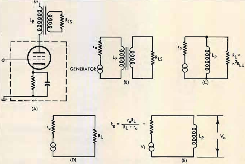
Fig. 6. Practical single-ended output circuit, (A), and its equivalents; (B), simplest form; (C), at low frequencies; (D), between 150 and 4000 cps; (E), final equivalent circuit at frequencies below 150 cps.
The output transformer itself is again a little more troublesome. The practical circuit is that of (A) in Fig. 4, two separate windings coupled by the iron core with the second winding supplying power to the loudspeaker. A start can be made by substituting a resistor RLS for the voice coil to give (B) of Fig. 4, but at the moment the next step will have to be taken on trust for later verification. The transformer ratio, usually denoted by the symbol n, has no effect on the frequency response, so to avoid having to multiply every impedance by n2 it is simpler to assume that the turns ratio is 1:1, the two windings having equal numbers of turns.
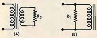
Fig. 4. When the ratio of primary to secondary turns equals n, the transformer and resistance of (A) can be replaced by (B), where R1= n2R2
As was seen earlier in this discussion, a load resistor of, say, 1000 ohms connected across the secondary of a 1:1 transformer has exactly the same effect as the same resistance connected across the primary winding, at least at the low-frequency end of the audio range. The practical circuit has now been reduced to the much simpler circuit of (C) in Fig. 6 the transformer and speaker voice coil being reduced to a resistor RL and an inductance Lp in parallel, the inductance being that of the transformer primary winding measured at some low audio frequency with the secondary winding open circuited.
If the generator is assumed to produce constant volts at all audio frequencies, the variation of voltage across RL and Lp will follow exactly the same law as the variation with frequency of the voltage across the loudspeaker voice coil in the practical circuit. This is the simplification that is desired.
Even without putting values on RL it is easy to see the sort of frequency response that will be obtained at low frequencies and to get an idea of the design steps that are necessary to get a flat response. With the generator (an a.f. oscillator) set to a near-zero frequency, current will flow around the circuit and the generator voltage will be dissipated across ra in series with RL and Lp in parallel. The voltage across RL, and Lp will only be a small fraction of the total generator voltage for the reactance of Lp. (XL=2πfLp) will be small.
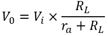
As the generator frequency is increased the reactance of Lp will increase (being directly proportional to frequency) until at some higher frequency the reactance will be much higher than RL. At, and above this frequency, the inductance Lp can be removed for it has no effect on circuit performance and the circuit then consists of the generator and two resistors, and RL. At these frequencies the equivalent circuit ra will be that of (D) in Fig. 6, the output voltage will clearly be:
and will be constant at this value at all higher frequencies (though see the later comment about high-frequency response). The requirements for a flat response are now fairly clear; the inductance of Lp should be sufficiently high to ensure that it does not shunt current away from RL for when the current in RL falls the voltage across RL falls and the frequency response begins to deteriorate.
The more technically minded will see a flaw in this reasoning. At those low frequencies where the reactance of Lp is low compared to RL the total circuit impedance will fall and the current drawn from the constant-voltage generator will rise and thus tend to maintain constant the voltage across RL and Lp. A detailed analysis shows that this compensating effect can be exactly allowed for by assuming that the generator resistance has a value lower than the slope resistance ra and in fact is equal to the valve slope resistance ra and the load resistance RL in parallel. The equivalent circuit then reduces to that of (E) in Fig. 6 and has the same voltage/frequency relation for Vo/Vi as the appreciably more complex circuit of (A) in Fig. 6, an effective demonstration of the advantages of equivalent circuits.
In a simple circuit such as that of (E) in Fig. 6, it is fairly easy to see that V0 will tend to approach Vi as the reactance of Lp becomes large relative to the resistor Rg. The reactance XL=2πfLp is directly proportional to frequency and thus it is clearly going to be difficult to maintain XL large compared to Rg, down to such very low frequencies as a few cycles per second. When transformers are used there is no alternative to accepting a frequency response that falls away at low frequency, but the frequency at which the falloff commences can be moved down to any desired frequency by increasing the value of Lp.
For reasons that will emerge later, it is usual to take as the cutoff frequency, that frequency at which the reactance of Lp equals the resistance Rg, this being the frequency at which the output is down by 3db. This is an arithmetical simplification rather than the point in the frequency range at which there is a significant cutoff, for the power output is only falling away at the rate of 6db per octave.
The shape of the frequency response, i.e. the relation between the ratio Va/Vi and frequency, is controlled by the ratio of XL to Rg and thus is unalterable. All output transformers have the same shape of frequency response but a good transformer is up to its level value at a very low frequency whereas a poor transformer does not achieve its "flat" value until a much higher frequency is reached. It is convenient to display this universal response in the form of a single curve Fig. 7, f0 being the frequency at which the reactance XL of Lp equals the resistance Rg. From this it will be seen that at this cutoff frequency where Fi/F0=1, the loss is 3db, but at half this frequency the loss is only 7db. Some of the simpler relations are given in Table I.
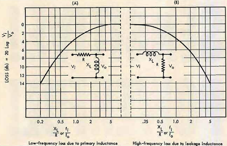
Fig. 7. Basic output transformer characteristics. f0 is the frequency at which the reactance XL is equal to the resistance R, and fl is the frequency at which the loss is to be determined.
Some realism is put into the picture by taking a look at the sort of values of primary inductance Lp that are required in practice if a flat frequency response is to be obtained. The two EL34's used in the earlier example require an anode-to-anode load of 3400 ohms and have a quoted slope resistance ra of 15,000 ohms, though as a push-pull stage is being considered the effective source resistance can be taken as 30,000 ohms. This is some ten times the required anode-to-anode load, a relation typical of tetrodes and pentodes and it results in the effective generator resistance Rg being 3000 ohms, only slightly lower than the required anode-to-anode load 3400 ohms. If it is decided to allow a loss of 3db at 50 cps the reactance of the primary inductance Lp must also be 3000 ohms at this frequency and Lp is then 3000 (2πx50)=10H approximately. If the 3-db point must be at 10 cps, then the inductance must be five times higher or 50 henries.
Practical Design
While dealing with a specific example it is worth calculating the number of turns and the size of transformer required to obtain the primary inductance suggested. Any required value of inductance can be obtained in either of two ways; a small number of turns on a large iron core, or a large number of turns on a small iron core. A large core and few turns should result in small signal power losses and a high price, with the converse being true if a small core and a large number of turns are adopted. The choice of core size is thus somewhat arbitrary unless the permissible power loss can be specified. An examination of the lists of some of the leading manufacturers shows that their high-quality transformers have an over-all volume of about two cubic inches per watt, suggesting that a 1½-inch stack of the laminations shown in Fig. 8 will handle 20 watts, though this is a point that will be checked more closely at a later stage when the distortion products are being studied.
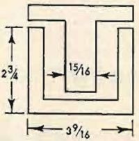
Fig. 8. Typical lamination shape.
The inductance of a coil wound on a closed iron core such as Fig. 3 is given (but only approximately):
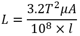 (3)
(3)
where:
- T = number of turns.
A = cross sectional area of core.
μ = permeability of core.
l = length of flux path.
(all dimensions in inches)
All the factors that appear in this formula are unambiguous except μ, the permeability of the core material, and this is difficult to specify because the permeability of any of the usual core materials is a function of the core flux density. Typical variations in permeability with flux density taken from the data sheets in a manufacturer's lists, are illustrated by Fig. 9, but experience shows that these permeability values are not achieved under working conditions. Data for these curves are invariably taken on ring samples without air gaps and after annealing. Laminations punched from the same material are rarely annealed after punching, are then assembled with air gaps that are small but unavoidable and finally used in transformers that carry small unbalanced anode currents, all important factors in reducing the permeability below the ring-sample value. It is more realistic to use permeability values that are half those read from Fig. 9 when calculating the winding inductance from above equation. The permeability will be seen to vary by a factor of about five times over a range of flux densities between 200 and 5000 gauss.
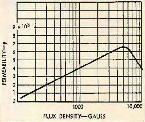
Fig. 9. Typical relation between core flux density and permeability for transformer steel.
The inductance of the primary winding will also vary with flux density by the same factor of five times, so that the frequency response will change with power output unless the inductance measured at some low flux density is adequate to maintain a flat response. The choice of an appropriate flux density and the related value of permeability is somewhat arbitrary but if a value for μ of 1500 corresponding to a core density of 500 gauss is used, the final performance is likely to be very acceptable. However, this problem of core density will come up again at a later stage when harmonic distortion is being considered.
Using the two cubic inches per watt figure it might be expected that a 1½-inch deep stack of the laminations shown in Fig. 8 would handle 20 watts with case. The core area of a 1½-in. stack is roughly 1½ sq. ins. and the iron path length 8 inches. Inserting these values into Eq. (3) shows that about 1100 turns are required to give an inductance of 10 henries while 2400 turns are necessary to obtain 50 henries. When harmonic distortion is considered at a later stage, it will be shown that in general the primary inductance required to hold harmonic distortion to an acceptably low limit automatically ensures a good frequency response.
The specified number of turns can be wound on to the core as a single coil having the secondary turns wound on top as in Fig. 10, though this is not the usual practice when a transformer having a high-quality performance is required. Why is this simple (and therefore low priced) construction not adopted? The answer is that the relative disposition of the two windings on the core controls the high-frequency performance, an aspect of the design problem that can now be considered.
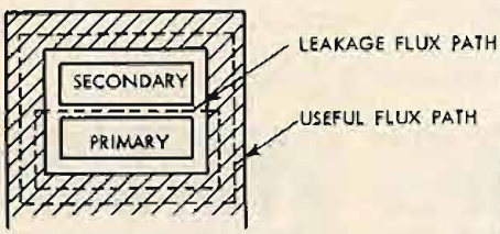
Fig. 10. Secondary wound over primary. Suitable only for transformers dealing with a restricted frequency range.
It is best approached by returning to the first section of this discussion dealing with the choice of turns ratio. It was then stated that all the magnetic flux produced by the primary winding was confined to the core and thus interlinked both coils. When the turns ratio and number of turns are being considered, this assumption is perfectly valid but when the high frequency performance is under examination the assumption is too sweeping. In the simple example of Fig. 11 magnetic flux lines emerging from the top of the coil have two alternative paths that can be followed back to the bottom of the coil. The designed path is that through the iron core, the path that is followed by the great majority of the magnetic flux. However, a very small proportion of the total flux leaks out of the iron and follows paths through the air as indicated, with the result that all the flux from the primary winding does not link with all the turns from the secondary winding. In a good transformer as much as 99.9 per cent of the flux from the primary winding links with the secondary but the remaining 0.1 per cent is responsible for the majority of the high frequency losses. A return to the equivalent circuit of (C) in Fig. 6 will ease the explanation.

Fig. 11. Paths of working and leakage fluxes in basic transformers
The primary inductance Lp appears in parallel with the load resistance RL but above a quite low frequency (50 to 150 cps) the reactance of this inductance becomes so high in comparison to the resistance RL that the current shunted off the load resistance becomes quite negligible. Above this frequency, Lp has no effect on the frequency response which is then determined by the resistances ra and RL and is thus independent of frequency, the conclusion arrived at when discussing the low-frequency performance. A flat frequency response is maintained up to frequencies of a few thousand cps but it then begins to fall away again, an effect that is not predicted by the equivalent circuits as they stand in Fig. 6. The missing element is an inductance that represents the effect of the magnetic flux which strays from the iron path and thus fails to link both coils. It is omitted from Fig. 6 because it has no effect on the performance of the transformer at low frequencies.
The clearest mental picture is obtained by assuming that the whole of the flux produced by the primary winding bypasses a few of the secondary tmns, leaving these few turns as an inductance outside the transformer and in series with the secondary load resistance RL. It is really immaterial whether we consider that 99 per cent of the flux links with 100 per cent of the secondary turns of that 100 per cent of the primary flux links with 99 per cent of the secondary turns, for it is the product of (flux)x(turns) that is important; but a clearer picture of the process is given by the second approach. The inductance that exists as a result of the failure of the primary flux to link all the secondary turns is generally known as the leakage inductance and can be measured on any of the standard a.c. bridges by short circuiting the secondary terminals and measuring the inductance that appears at the primary terminals. The same final answer is obtained if the primary terminals are shorted and measurements made at the secondary terminals but the two measurements will differ in the ratio of the (turns ratio)2.
The general effect of this leakage inductance on the frequency response is now fairly easily seen from a consideration of its position in the equivalent circuit where it appears in series with the secondary load resistance RL as in Fig. 12. As the signal frequency rises, the reactance of LSC rises proportional to frequency, eventually becoming comparable in value to the secondary load resistor RL and with further increase in frequency the reactance of LSC will exceed RL . The signal voltage produced by the generator is now divided between three circuit elements - ra the equivalent resistance of the generator, LSC the leakage inductance, and RL the secondary load resistance - and therefore V0 will fall off with increase in frequency at the rate of 6db per octave.
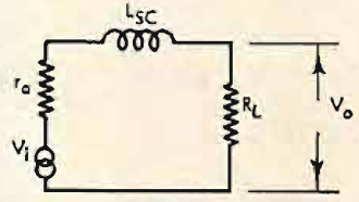
Fig. 12. Equivalent circuit at frequencies above 4000 cps.
The point in the frequency range at which the falloff begins to be significant (rather arbitrarily, the frequency at which the response is 3db down) is a function of the ratio of the reactance of LSC to the combined total circuit resistance ra + RL. When XSC = 2πfLSC = ra+RL the loss is 3 db and increases at the rate of 6 db per octave as shown at (B) in Fig. 7. The similarity between the relations governing the high-frequency loss and those governing the low-frequency loss will be apparent on comparing (A) and (B) in Fig. 7.
Leakage Reactance
Clearly if the response is to be well maintained up to the highest frequencies, LSC must be reduced to a minimum so the factors that affect LSC will now be considered. Little thought will be required to decide that the leakage inductance will increase as the number of turns on the windings increase, following the normal law that inductance is proportional to (turns)2. Advantage cannot be taken of this relation to reduce the leakage inductance, for as we have seen earlier the total turns are fixed by the response that is desired at the low-frequency end of the range. The alternative course of action is to reduce the amount of leakage flux from the primary that fails to couple with the secondary winding. This is a question of bringing the secondary winding as close to the primary winding as is physically possible. Some possibilities will be considered.
The worst possible arrangement is that of the elementary transformer of Fig. 11 where the primary winding is arranged on one limb and the secondary winding on the other limb. Leakage flux then follows the path shown and may amount to an appreciable fraction of the total flux. It may be greatly reduced by winding the secondary on top of the primary winding as shown in Fig. 10 and abandoning the core type of lamination shown in Fig. 11 in favour of the shell type of Fig. 8. Magnetic leakage then follows the path shown in Fig. 10 and will obviously be a great deal less than in the simple arrangement of Fig. 11. Further reduction in leakage may be achieved by dividing either winding into two halves and disposing them about the other winding. This technique of sub-division may be carried still further, both primary and secondary windings being sub-divided into sections and interleaved. Some typical arrangements are shown in Fig. 13. That of (B) has particular advantage in push-pull circuits in that the two half primaries can be made to have the same resistance by using P/4 and P/4 in series for one half primary, with P/2 for the other half. This also equalizes the leakage inductance from either half primary into the secondary.
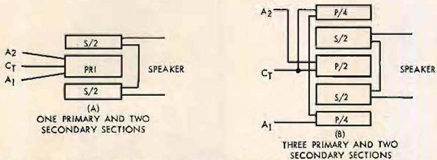
Fig. 13. Further subdivision of windings to reduce leakage reactance .
There are two alternative approaches to the problem of reducing leakage inductance that are worthy of comment. Reduction of the spacing between the primary and secondary sections is clearly an advantage but a limit to this technique is set by the necessity of providing interwinding insulation between the sections capable of withstanding the plate supply voltage and signal voltage excursions. It is usual to operate amplifiers with the secondary winding at or very near ground potential but with the primary winding at B+ potential. The newer insulations with high dielectric strengths that are now appearing offer considerable advantages in reducing the thickness of the intersection insulation.
The leakage inductance of any particular arrangement of coils can be calculated with a moderate degree of accuracy and it is worthwhile examining the relationship for the light it throws on the factors responsible for leakage. A simple formula that gives good agreement with measured values is:
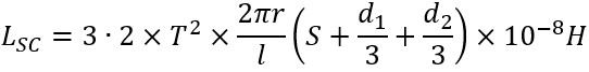
the symbols having the meaning shown in Fig. 14. From this it will be seen that the leakage inductance is increased by an increase in the radius r of the winding, by an increase in S, the spacing between coils or decreased by an increase in l, the wound length of the coil. A lamination having a long narrow window such as that of (A) in Fig. 15 will give a lower leakage inductance per turn than one with a square window such as that at (B) . This is not quite the advantage that it appears at first sight, for laminations with long windows tend to have long iron paths and thus have a lower primary inductance Lp per turn than one with a square window. Nevertheless there is an advantage to be gained by an appropriate choice of lamination shape.
Fig. 14. Dimensions required for calculation of leakage inductance
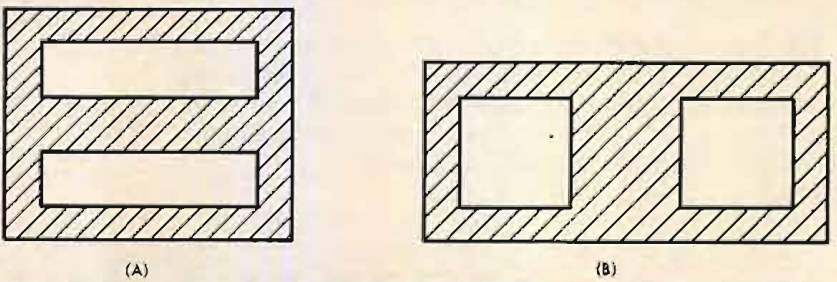
Fig. 15. laminations having long windows (A) have lower leakage inductance than those having square windows as at (B).
Distortion
The last performance characteristic to be discussed is the generation of harmonics and intermodulation distortion by an iron-core device. This is not such a well understood subject and in consequence will be covered in rather greater detail than was thought necessary for some of the earlier characteristics.
How does distortion arise in an ironcored device? Fundamentally it is due to the non-linear relation between the magnetizing force H and the resultant flux density B produced in the iron core, but it is also due to the presence of hysteresis in magnetic materials.
In an ideal magnetic material, the magnetizing force H would produce a magnetic flux density B proportional to H. Thus if H were doubled (by doubling the current or the number of turns) B should double. Moreover, B should have the same value for any particular value of H, irrespective of the direction in which the current flows in the magnetizing coil. Neither of these requirements is met in a magnetic circuit that consists wholly of magnetic material. What does happen is illustrated by Fig. 16, a typical B/H relation for a transformer steel.
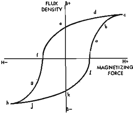
Fig. 16. Typical B/H relation for iron laminations
Starting from zero current in the magnetizing winding, but with the iron path magnetized by the previous cycles of the supply, the flux density in the iron rises roughly proportionately to the current up to point a in Fig. 16 then less than proportionately from a to b, and finally saturates at c; very large increases in magnetizing current are then required to produce very small increases in flux. If the direction of the current flow is reversed, B commences to fall, not along the path c, b, a, but along a new path, d, e, f, where the values of B are always higher than were obtained for the same values of H when H was increasing. The magnetizing current must be reversed to reduce B to zero at f, a symmetrical path g, h, i, k, l then being traced as H increases to a negative maximum, reverses, and returns to zero. The point of importance is that the path followed by the value of B encloses an area instead of merely following a straight line. From the B/H relation of Fig. 16 it may be deduced that a sinusoidal magnetizing current in the primary coil will not produce a sinusoidal flux waveform in the iron circuit. As the secondary voltage is proportional to the rate of change of flux, a sinusoidal secondary voltage can only be produced by a sinusoidal flux waveform and this will in turn only be produced by a nonsinusoidal current wave in the primary winding.
At this stage it would appear that an impasse has been reached for distortionless reproduction demands that a sinusoidal voltage on the grid of the output valve produces a sinusoidal voltage across the output transformer secondary, though it has been shown that this result can only be achieved by supplying a non-sinusoidal current to the transformer primary. However, the impasse is only the result of shallow thinking about the problem as it may be shown that if the impedance of the source is very small, a sinusoidal voltage applied to the transformer primary will result in a nonsinusoidal primary current, a sinusoidal flux waveform, and a sinusoidal secondary voltage. The significant point is contained in the phrase "if the resistance of the source is very small" and the question that immediately jumps to mind is, how small? There are few abrupt discontinuities in nature and it is unlikely that the distortion will prove to be zero when the source resistance is zero and yet rise sharply for very low values of source resistance. Common sense is right on this point. A detailed analysis shows that the percentage distortion is related to the ratio of circuit resistance to the inductive reactance of the primary winding of the transformer and is a function of the maximum flux density at which the iron is worked. This latter result is to be expected for there is a fair degree of proportionality between H and the resultant B if the flux density is not allowed to exceed point a in Fig. 16. Unfortunately a low flux density means a large core and an expensive transformer.
The advantages of a low-resistance source in minimizing harmonic distortion are less obvious and need a more detailed explanation. If a generator of zero resistance and a sinusoidal voltage waveform supplies current to a resistive load, both the current and voltage have sinusoidal waveforms. When the resistance load is replaced by an inductance the voltage waveform remains sinusoidal but the current waveform is distorted by just the right amount to produce a sinusoidal flux waveform and thus a sinusoidal secondary voltage waveform. The primary current wave is then found to contain a high percentage of third, fifth, and seventh harmonics. In an intermediate condition when the circuit contains some resistance, the current drawn from the source is less distorted but the distortion of the voltage waveform is increased. In general any resistance in the circuit prevents the inductance drawing the harmonic currents it requires to maintain a sinusoidal flux waveform. If a sinusoidal flux waveform is not maintained then the waveform of the secondary voltage will be non-sinusoidal.
When considering the low-frequency response of a transformer it was shown that the resistance that controls the response is the parallel combination of the source and load resistances. The same parallel combination also controls the harmonic distortion that is generated. If the transformer is a poor example with high resistance windings these winding resistances must be added to the load resistor before working out the parallel combination.
Most of the manufacturers of transformer steels have produced curves showing the relationship between distortion and the ratio of the effective circuit resistance to the reactance of the primary winding. Typical curves for a 4 per cent silicon steel commonly used in high quality transformers are shown in Fig. 17. The most significant information to be obtained from the curves is the very high distortions that occur even at low flux densities when the source resistance is comparable with the reactance of the transformer primary winding. Earlier in the contribution it was shown that a transformer having a primary inductance of only 10 henries would have a frequency response only 3db down at 50 cps when used with two EL34 valves working into a load of 3400 ohms. It is interesting to calculate the harmonic distortion that is produced if such a transfomer is used.
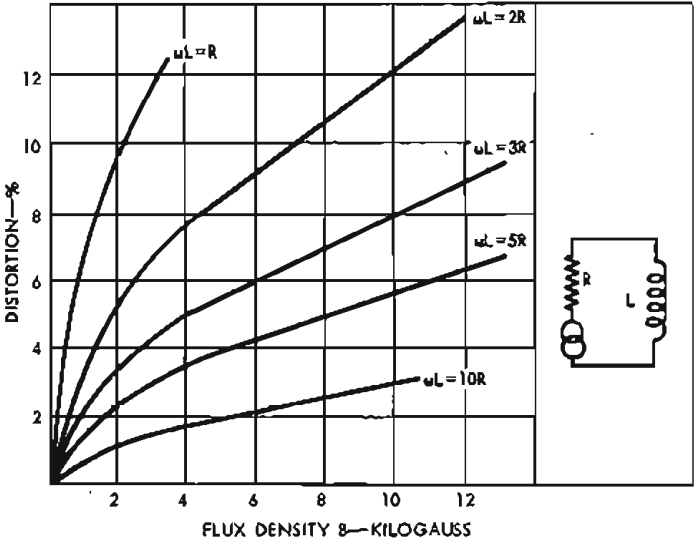
Fig. 17. Third-harmonic distortion in the voltage across L as a function of the flux density B for values of ωT/R
At a frequency of 50 cps an inductance of 10 henries has a reactance of 3140 ohms, approximately equal to the effective generator esistance when using two EL34's in push-pull. The left hand curve for ωL = R is then appropriate. The core flux density when the power output is up to the rated figure of 20 watts may be computed (see appendix) to be approximately 10,000 gauss, a value that is well off the curve but it will be seen that the harmonic distortion is up to 12 per cent for a fiux density of only 3000 gauss and continues to increase rapidly at higher flux densities, a quite intolerable r esult for a high-quality transformer.
The alternative discussed was to use a transformer having a primary inductance of 50 henries and thus having a response that is flat down to about 10 cps. Reference back to the earlier discussion indicates that such an inductance would be achieved with a primary winding of 2400 turns on the same core. The increased turns bring the core flux density on full load (20 watts) down to about 4500 gauss, the core material having an effective permeability' of about 3200 at this fiux density. The resultant primary inductance has then risen to about 110 henries, making the ratio of primary reactance to effective source resistance approximately 11.5 at 50 cps. Extrapolating the curves on Fig. 17 it is found that the harmonic distortion is about 1.7 per cent at full load, a very considerable improvement in performance.
These figures make it quite clear that when a high-quality amplifier is being designed, the frequency response must extend well below the nominal lower frequency limit required by the signal spectrum if harmonic distortion is not to be intoler ably high on low-frequency sIgnaIs. In this particular, though typical, example, the response must be flat down to 10 cps in order to achieve distortion values as low as 2 per cent at 50 cps.
The reduction of fiux density appears advantageous in reducing harmonic distortion but to a great extent this is an illusory advantage. Provided that the fiux density is kept below about 5000 gauss at full rated power, there is little to be gained by further reduction, for though reference to Fig. 17 would suggest that the distortion is falling as the fiux density is reduced, it must be remembered that μ and in consequence the primary inductance Lp and the ratio of ωL to R is also falling. Thus there is no very significant reduction in the percentage harmonic distortion percentage as the maximum flux density is reduced. None of the alternative core materials at present available offer hope of any significant improvement in this situation.
The curves of F ig. 17 also suggest that distortion can be greatly reduced by decreasing the effective resistance of the source. At first thought, tetrodes and pentodes appear appreciably worse than triodes in this respect but further investigation does not always support this view. Two EL34's have an effective slope resistance of 30,000 ohms as pentodes in push-pull but only 6000 ohms connected as a pair of triodes, but it should be remembered that the effective source resistance from the point of view of harmonic generation is the parallel combination of valve resistance and load resistance. As pentodes, two EL34's require an anode to anode load of 3400 ohms, making tha effective source resistance about 3000 ohms. As triodes the valve slope resistance had dropped to 6000 ohms but the optimum load has risen to 10,000 ohms, making the effective source resistance about 3,700 ohms. Thus in this instance triode connected valves are slightly worse than the same valves pentode connected.
Ultra linear operation of pentode or tetrode valves offers a significant reduction in effective source resistance, another reason for the obsolescence of "straight" operation of pentodes or tetrodes. Negative feedback, either over the whole amplifier as a distottion reducer, or from the anodes of the output valves back into the cathode circuit of an earlier valve as a source impedance reducer, has great advantages and is in fact the only method of obtaining distortion values in the region of 0.1 per cent at full rated load.
Appendix
The flux density B in a transformer core can be calculated from the following equation:
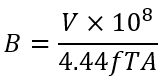
where:
- B = flux density
- V = voltage across winding
- f = frequency
- T = number of turns on winding
- A = core area sq. cms.
In the example used in the discussion V is the voltage developed across the anode load RL of 3400 ohms at the rated output power of 20 watts. This is:
![]()
Using a core having an area of 1.5 sq. ins. (10 sq. cms.) and the 2400-turn winding, the core fiux density B at a frequency of 50 cps is:

At this value of fiux density the effective permeability may be taken as 3200 and the inductance of the 2400-turns winding is then:
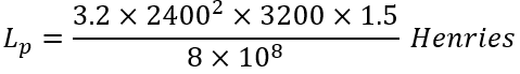
L at 50 cps = 34,400 making ωL/ R = 11.5.
The distortion where B = 4900 lines/sq. cm. and L / R = 11.5 is, from Fig. 17, approximately 1.6. percent.
")
")
")
")
")