Home
Xindak MT-3 amplifier
- Details
- Category: Photo gallery
- Hits: 8384

Grzegorz 'gsmok' Makarewicz
A tube amplifier with the so-called middle shelf. Traditional circuit solution with non-traditional, rarely used ability to switch between triode and pentode modes. I was encouraged to post a short description and a not-so-short set of photos by the information appearing in many places that it is an automatic polarity amplifier that does not require the adjustment of the quiescent current of the output tubes. Well, it is not true and I warn users of this amplifier against a lighthearted approach to this important issue.
The first photo shows the amplifier which heats up during the procedure of adjusting the quiescent currents after replacing the electron tubes in the amplifier's power stage.

Looking for information about the XINDAK MT-3 amplifier, I was surprised to find that despite a large number of sales offers and positive opinions, there is practically no detailed data on its SAFE operation. Replacing the electron tubes in a tube amplifier is not the same as changing a toothbrush. It must be approached in a thoughtful and, above all, safe manner. And here I come back to the introduction. In one of the audiophile magazines (not Polish, fortunately) I found an opinion expressed by an "expert" on the subject that due to the automatic polarity of electron tubes, this amplifier is a particularly good proposition for those who like to experiment with electron tubes. They can replace them at will without the need for any regulations. I have very little hair left on my head, but this remnant was brought to attention when I read about it. As an example of the dangers related to the replacement of electron tubes, let us use the fact that after replacing the tubes in the amplifier, which I present here without any regulation, the measured currents were from 35mA to 80mA for individual tubes.
Radio dla Techników i Amatorów (Radio for Technicians and Amateurs) 1946/03
- Details
- Category: Radio dla Techników i Amatorów
- Hits: 6703

RADIO dla Techników i Amatorów, Rok I, Marzec 1946r., Nr 1.
(RADIO for Technicians and Amateurs, Year I, March 1946, Number 1)
- From the editorial office (1)
The new era of nuclear energy that is unfolding before us must now put its tasks on the agenda: Technical culture should become the property not only of individuals, but also of broad strata of our society. Acquiring certain habits, methods and technical knowledge is also a basic condition for creating a sufficiently wide team of people who can actively cooperate in the reconstruction and construction of radio and television in a democratic Poland.
The tasks facing our radio technicians are enormous, not only because of the necessity to reconstruct what was, but also to create what has not been there so far, i.e. the universality of radio.
These were the reasons that led us to the issue of the new monthly magazine for technicians and radio amateurs - "RADIO" - Review of issues in the construction of receivers (2)
The transmitter and receiver are important elements of radio signal transmission. Technical improvements are made to the transmitting and receiving devices in order to reach the limits of practically achievable possibilities. On the receiving side it is necessary to adapt to the conditions created by the transmitting side and to the conditions of the propagation environment.
The conditions on the transmitting side depend primarily on the lack of available wavelengths. In amplitude modulation using both sides of the spectrum to avoid mutual interference, the power of the transmitters and the wavelength spacing are reduced more than otherwise desirable.- Influence of progress in the construction of electron tubes.
The progress in the construction of electron tubes in the last 10 years has been taking leaps and bounds through many implementation stages, differing not only in terms of electrical parameters, but also in terms of external performance, connections to the pedestal and construction of the pedestal. In this way, almost every year, a large number of tubes of various types had to be withdrawn from circulation. The newly constructed vacuum tubes were immediately applied to new types of radio receivers, and rarely any type of radio receiver was manufactured for more than one year.
- Influence of progress in the construction of electron tubes.
- Frequency modulation (6)
In recent years, frequency modulation has gained a lot of importance and has found numerous applications. Suffice it to say that currently in America, radio listeners are called to buy radio receivers that enable reception of radio waves modulated in this way, because a number of radio stations will soon use frequency modulation. - New English radio on three electron tubes (10)
A new radio receiver from one of the companies in Cambridge has appeared on the English market. Its description is given in "Wireless World". We believe that our readers will be interested in the description of this radio receiver, if only because of the desire to find out what types of radio receivers will have a chance of success in the post-war period.
- Schematic diagram of the radio receiver.

New English radio receiver on electron tubes (schematic diagram).- Some design details.
The base of the structure can be very easily removed from the box. The loudspeaker is easy to disconnect as it is connected via plugs. The knobs on the front of the radio receiver are designed in such a way that they can be pressed in.Read more: Radio dla Techników i Amatorów (Radio for Technicians and Amateurs) 1946/03
Simple measurement of the number of turns in a transformer
- Details
- Category: Radio dla Techników i Amatorów
- Hits: 9276
Simple measurement of the number of turns in a transformer.
RADIO Miesięcznik dla Techników i Amatorów, Rok IV, Styczeń-Luty 1949r., Nr 1/2
(RADIO Monthly magazine for Technicians and Amateurs, Year IV, January-February 1949, No. 1/2)
(Trioda website is not responsible for the content of the article)
We often have difficulties with determining the number of turns in a transformer. In many cases, unwinding the transformer and recalculating the turns in this way is pointless, especially when we want to use one of the factory windings in an undamaged transformer, and the other, based on the calculation, to be wound up.
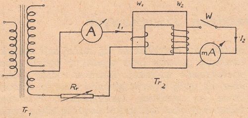
Fig. 1.
Fig. 1 shows a system with which we can easily determine the number of turns in a transformer winding, without the need to unwind it with sufficient accuracy for practice.
On the core of the transformer, one winding of which we want to examine, we wind one coil of thick (about 1mm) insulated wire. This one turn is connected through an adjustable resistor Rr and through an ammeter [A] for alternating current, with the heating winding of some other transformer Tr1 (eg with a voltage of 4V), which we will use as the current source in our measurement. The winding of the transformer Tr2, on which the measurement is performed, is connected through the switch [W] with a sensitive milliammeter [mA] for alternating current. First, leave the tested winding circuit open (the switch [W] is open).
Read more: Simple measurement of the number of turns in a transformer
Radioamator (Radioamateur) 1950/10
- Details
- Category: Radioamator
- Hits: 7795

Radioamator, październik 1950r., rok I, numer 10
(Radio amateur, October 1950, volume I, number 10)
Diagrams of receivers types: Nora W.16 Tosca and Nora GW. 16 Tosca (cover page 2)
The diagrams below show connections in receivers manufactured by 'Nora' of the "Tosca" "W16" and "GW16" types. Both receivers are two-tube with a third rectifier, two-range (medium and long waves) and belong to the category of simple devices. They have the same receiving frequency, but they differ in the method of supplying electricity and the types of tubes. The "Tosca" "W16" receiver is powered by alternating current from the lighting network and has the first AF7 type tube that acts as a detector. The second - is a loudspeaker type AL4 The AZ1 rectifying tube works in an anode power supply.

The "Tosca" "GW16" receiver can be supplied with alternating or direct current from the lighting network. It has receiver tubes that correspond to the types of electric tubes in the first camera, i.e. detector - CF7 and speaker - CL4. The power supply uses a CY1 rectifying electron tube and the "Urdox" U920 current regulator.

Both devices have volume control and selectivity control, which is achieved by changing the capacitance of the differential capacitor located in the antenna circuit. They also have built-in eliminators, which allow for clear reception of foreign stations, undisturbed by local radio broadcasts. The timbre of the sound is regulated by switching on and off the appropriate permanent capacitor located in the anode circuit of the loudspeaker tube. Both devices have identical boxes.
Soviet television (1)
In 1922, when a radio broadcasting station in New York had a power of less than 1.5 kW, a 12 kW transmitter was built and put into operation in the Soviet Union. In the same year 1922, the Soviet Union took the first place in the world in terms of the power of transmitting stations, ahead of other countries' radio technology, which often drew on the experience of Soviet engineers. For example, in the words of the Americans themselves, the Soviet system for building super-powerful transmitters was used to build a 500 kW station near Cincinati. A modulation system developed in the USSR was also used in the New York TV transmitter.
Excellent results were achieved in the Soviet Union and in the field of television.
The theoretical foundations of television were prepared in 1888 - 1890 by many Russian scientist, physicist A.G. Stoletov, who studied the effect of light on the electrical conductivity of gases and constructed the world's first photoelement.
...
The rise of the technical and economic power of the Soviet Union, the achievements of Soviet science created the conditions for a jump in the development of Soviet television from the standard of 343 lines to 625 lines, which was ahead of Europe (405) and America (525 lines).
The transition of the Moscow TV station to a new standard was connected not only with increasing the clarity of the image, but also with the expansion and increased power of the devices.
The task of significantly increasing the technical and operational capabilities of television was completed with full success.
Soviet readers were surprised to read in a magazine from an English news outlet in the USSR recently that England still used the pre-war standard on television and that it was considered "completely satisfactory"...
Let's learn radio technology - Cathodes (3)
The cathode of the electron tube, in order to work normally, that is, to emit free electrons to the outside, must be heated to a certain strictly defined temperature. The cathodes of the tubes are heated by electric, direct or alternating current, the "direct filament" tubes are designed rather for direct current operation, while the "indirect filament" tubes may be heated freely, using direct or alternating current. The electric power of the filament current lost as heat in the cathode is calculated by multiplying the filament voltage in volts by the filament current in amperes. For example, if we have a 4 volt electron tube whose filament current is 1 ampere, then the filament power is: 4 x 1 = 4 watts. Filament is needed in order to keep the cathode temperature constant. As the hot cathode radiates heat to the outside and thus cools down, it is still necessary to supplement these deficiencies by supplying electricity from the filament source..
The power needed to heat the cathode in the electron tube depends on the surface of the cathode and the temperature at which it works. The least amount of glow power is required for electron tubes with an oxide cathode because, as we know, the operating temperature of the oxide cathodes is not high. The cathode area determines the amount of electron emission. High-emission electron tubes require large-area cathodes, which entails high filament power. Electron tubes with low emission have a small area and therefore the required filament power is small. Knowing the glow power of the electron tube, we can approximately determine its maximum emission. For one watt of power lost in the cathode, as we know, in the case of the oxide cathode, we can count about 100 mA of emission, so in the case of an electron tube with a filament power of 4 W, the maximum emission current will be in the order of 400 mA.
...
Tubes with the same filament voltage are connected in parallel to the power source, similar to e.g. electric bulbs for the lighting network.
...
Parallel connection of electron tubes is used in alternating current battery and mains devices - generally with low-voltage electron tubes.

On the other hand, in DC or universal apparatus, i.e. DC and AC, all filament filaments are connected in series. Since in this case the same current flows through all the tubes, all tubes used in such a system must be built for the same filament current.
...

However, in individual cases, instead of e.g. one 100 mA tube, two parallel connected 50 milliampere tubes may be connected to the power supply circuit. The power supply of tubes connected in series with each other must be at a nominal current. If the sum of the voltages of all serially connected tubes is lower than the voltage of the supplying source, then we have to connect the resistance in series with the tubes and adjust the current to the nominal value. Instead of a constant resistance of an appropriate value, an iron-hydrogen resistance called "Urdox" is usually used, which works automatically, i.e. it adjusts the filament current to the appropriate nominal value regardless of the voltage supply.

...
Now that we know the properties of the cathodes, let's get acquainted with the leads of the electron tubes and see what terminals the filament filament ends are connected to..
Acoustic tube amplifiers
- Details
- Category: Radioamator
- Hits: 9600
Acoustic tube amplifiers
Radioamator, Rok XI, Luty 1961, Nr 2 (Radioamateur, Year XI, February 1961, No. 2)
Simple 2-tube amplifier
The output power of this amplifier is 3W with a harmonic distortion coefficient of 2.5%; the sensitivity of the amplifier is 150mV. In order to minimize mains hum, the cathode of the first tube is grounded (Fig. 1), and the negative voltage is obtained due to the voltage drop caused by the grid current in such a system is very small, so the input resistance of the tube is approximately half the leakage resistance.
The output stage is conventional with negative feedback for adjusting the frequency response. In the left position of the potentiometer in the negative feedback circuit, the frequency response is raised for the lowest and highest frequencies of the acoustic band. In the right position of the potentiometer slider there is a significant weakening of higher frequencies, starting from 1000Hz. Any rectifier with a voltage of about 240V and a current of up to 40mA can be used to power the amplifier. The rectifier should have a ripple smoothing filter. The output transformer of the amplifier can be made on a core with a cross-section of 16x16mm, the primary winding should have 3500 wire turns 0.15 in diameter, and the secondary winding - 165 wire turns 0.65 in diameter (for a loudspeaker with a resistance of 4 ohms).
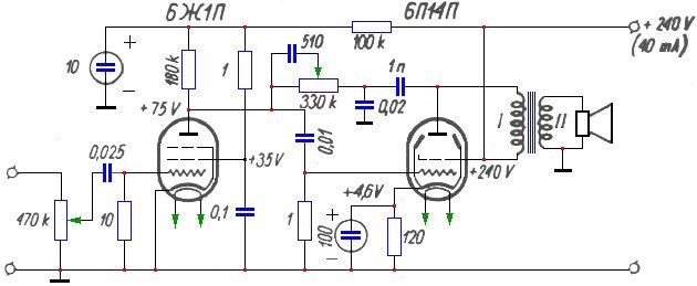
Fig. 1.
Amplifier with an output power of 3W
This amplifier has better quality paremeters than those described previously, and besides, a separate adjustment of the frequency response in the range of low and high frequencies of the acoustic band. The output power of the amplifier is 3W with a harmonic distortion not exceeding 1.5%. The frequency response is adjustable within ± 16dB at 100Hz and within ± 14dB at 10kHz. Amplifier sensitivity - 100mV.
The schematic diagram of the amplifier is shown in Fig. 2. The negative feedback loop contains RC elements selected in such a way that the strongest negative feedback falls on the middle part of the amplifier's passband. As a result, the gain in the 400-2000Hz range is lower by about 16dB than for low and high frequencies of the acoustic band. To adjust the frequency characteristics of the amplifier, two potentiometers at its input are used. With the help of a potentiometer with a resistance of 1Mom, the characteristic can be adjusted in the high frequency range. Similarly, the 4.7Mom potentiometer controls the characteristics in the low frequency range.
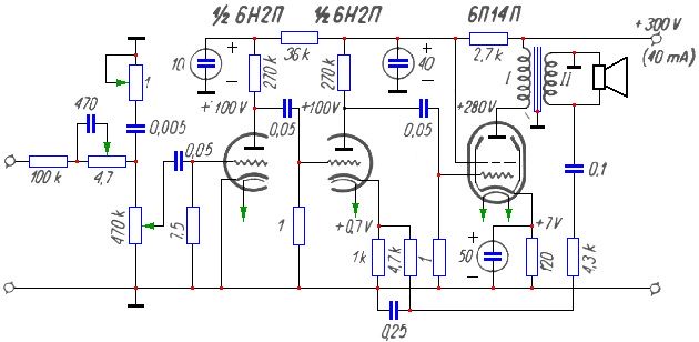
Fig. 2.
Speaker amplifier "3L"
- Details
- Category: Radioamator
- Hits: 8502
Speaker amplifier "3L"
eng. Czesław Klimczewski
Radioamator, Rok III, Styczeń 1953r., Nr 1 (Radioamateur, Year III, January 1953, No. 1)
In issue 11 of our magazine there is a description of a loudspeaker pickup (amplifier) with two electron tubes operating in a push-pull arrangement using a transformer that controls these tubes. As it is not always possible to purchase such a transformer on the market, winding it presents a certain difficulty - a description of the amplifier is now given, in which the function of the so-called the "phase inverter" is not accomplished via a transformer but via a tube. The amplifier also does not have a low-frequency choke for filtering the rectified pulsed current, but a resistor with a resistance of 3000 ohms and a load capacity of about 5 watts. Such a resistor is easy to buy, or you can wind it yourself on a porcelain or glass tube.
Due to the non-use of a transformer and choke, the cost of the described amplifier is relatively low and its assembly is easier. This amplifier, made strictly according to the given diagrams, will work perfectly and can power one or more speakers with a total power of about 25 watts.
Fig. 1 shows a schematic diagram of the amplifier. This amplifier is adapted to work with a radio receiver with sockets for connecting an additional loudspeaker. These sockets must be connected to the amplifier in such a way that one of them, marked with a "plus" sign, should be connected to the socket marked with a "b" sign. If there is no marking on the receiver housing, then the sockets of the additional loudspeaker are connected in it in such a way that the amplifier can be connected freely without paying attention to the compatibility of connections. This attachment can also be combined with a low-frequency amplifier, the so-called "preamplifier" to obtain more power for driving the loudspeakers. For this purpose, the described amplifier uses a W1 switch that turns off the resistance R1 = 5000 ohms, so that it can be connected to a radio apparatus or an amplifier having a small "output" resistance - of the order of 500 ohms or a large one - of the order of 5000 ÷ 6000 ohms. Radio apparatuses have the output resistance of the additional loudspeaker, usually high - in the order of 6000 ohms.
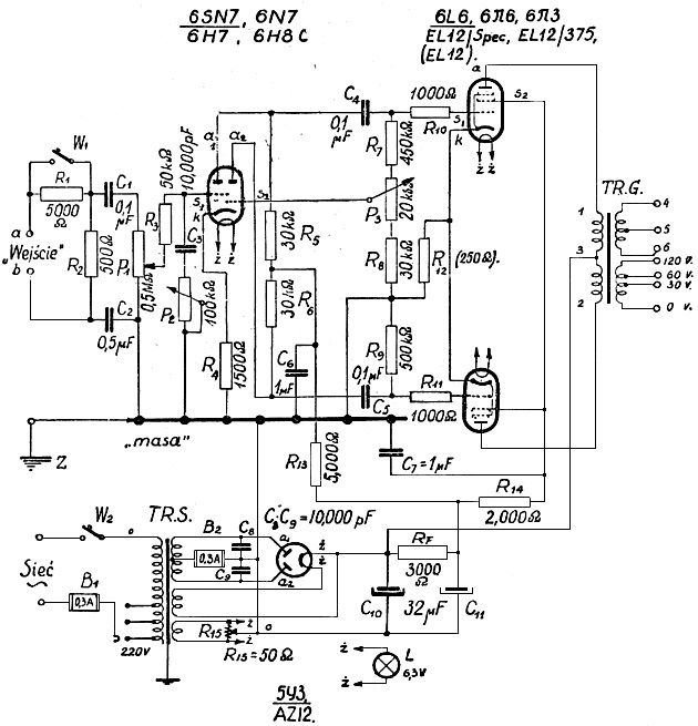
Fig. 1.
The voltages received from the spool of the potentiometer P1 are sent to the control grid of the first triode of the tube (6SN7) through the resistor Rs = 50,000 ohms (50K), which is a eliminator for possible parasitic currents. This grid is also connected to the 10.000 pF capacitor, which is connected via P2 = 100K potentiometer to the grounded base of the device ("ground"). This potentiometer is used to adjust the "timbre" of the amplified programs.
Radioamator (Radioamateur) 1950/09
- Details
- Category: Radioamator
- Hits: 7610

Radio amateur, September 1950, year I, number 9, price PLN 60.
CONTENT (1 cover page)
- Interference with radio reception.
- Let's learn radio technique.
- It's not difficult at all.
- Home loudspeaker installations.
- Radio probe.
- Diagrams of radio receivers T813.W and T813.GW.
- Rationalizer corner.
- Radio communications in the USSR.
- Radio engineering vocabulary.
- Editors' replies.
Diagrams of radio receivers types T813.W and T813.GW (cover page 2)
The presented diagrams show two popular radio receivers type T813.W and T813.GW.
The first of them, T813W type, is powered by alternating current, and the second - T813GW - by alternating or direct current from the lighting network. Receiving parts of radio receivers are assembled according to the same diagram. These are "simple", three-range, single-circuit receivers.
The T813W receiver has an AF7 electron tube, which acts as a detector, and an AL4 radio speaker tube.

Radio receiver type T813.W.
In the T813GW receiver the detector tube is VF7 and the speaker tube is VL4.

Radio receiver type T813.GW.
Both receivers use the same rectifying electron tube - AZ1. Both receivers have sockets for connecting a turntable, apart from the type, the T813W device has a switch that allows to reduce power consumption from the lighting network when listening to a strong local station.
Likewise, both receivers have permanent eliminators to eliminate interference in reception caused by the strong local station program. The setting of the waveband switches is adapted to receiving long waves.
The presented diagrams also show the voltages and currents (for both types of power supply) that should be in the individual circuits of the receiver. Knowledge of these values should facilitate the repair of the receiver.
The diagram of the radio receiver T813GW shows the connections of contacts on the board of the network switch for easier orientation during its repair.
Peace will win the war (1)
"The struggle for lasting peace, for the victory of fraternal coexistence among nations - is the most important task of the present generation. No one should doubt the final victory of this struggle, because the peace movement has become a movement of hundreds of millions of people today, and the ranks of active peace defenders are growing steadily. Nothing can stop the growth of this movement, because it is a movement for truth and justice in human relations. The strength of this movement is also based on the ever-increasing strength of nations liberated from capitalist violence, led by the mighty Soviet Union, led by the great peace standard-bearer Generalissimo Joseph Stalin. The Polish nation joins this fight for peace completely and with an unchanging will to win".
In these words delivered on September 2 this year to the delegation of the First Polish Congress of Peace Defenders - Bolesław Bierut, the President of the People's Republic of Poland, included the content of the struggle for peace waged today by the whole world. This was also the content of the session of the Warsaw Congress.
Interference with radio reception (2)
Industrial disruptions.
Contrary to atmospheric disturbances, the influence of which on radio reception is so strong that it often forces the device to be turned off and which almost cannot be avoided (see No. 6 of the magazine) - industrial disturbances can be effectively eliminated and can only be forced to abandon radio reception.
Interferences of this type are local in nature and come from electrical devices such as: AC and DC motors, vacuum cleaners, medical and hairdressing appliances, circuit breakers, etc. They most often manifest themselves in the form of tiring ear growling. Produced by the aforementioned devices - parasitic waves disrupting radio reception, they are most severe in large cities, industrial and health centers, where they create a "thick fog" which must be penetrated by radio waves sent into space by antennas of transmitting radio stations.
Let's learn radio engineering (5)
Cathode of electron tubes.
The basic electrode in any vacuum tube is the cathode. In order for the cathode to emit electrons, it must be heated to a relatively high temperature - several hundred or even over a thousand degrees. The cathode is heated with an electric, direct or alternating current. We have learned about two types of cathodes, namely direct heated cathodes and indirectly heated cathodes.
Direct-heated cathodes are usually made of tungsten wire, which in the case of small receiver tubes is usually activated by a track or bar, i.e. has an active layer of thorium or a layer of barium oxide on its surface in order to increase the emission efficiency of the cathode. The cathode wire on small receiver tubes is extremely thin. Its diameter is 10 microns, or 0.01 mm, while with high-power transmitting tubes whose emission reaches the value of 100 and more Amps, the diameter of the cathode fiber may be several millimeters..
...
Filaments for filing direct-glow electron tubes must be carefully suspended in the tube, and the finer the thinner the wire is. Usually, the cathode wire is suspended in one plane and it is in the shape of the letter "M" or the letter "V" inverted. The wire is suspended on springs, which is why it is subjected to a certain tension. This tension guarantees the suspension of the cathode in one plane and prevents the lateral warping of the wire during its heating due to thermal elongation of the wire. This ensures a constant distance between the wire and the anode or other electrodes in the tube (Fig. 1a and Fig. 1b).

Fig.1.
Fig.1a gives an example of a battery tube cathode suspension with a low filament current, i.e. having a very thin wire, while Fig.1b refers to a direct-glow rectifying tube in which a nickel tape covered with an active oxide layer is used. Such a tube generally has a relatively high emission. Pure tungsten wires without an active layer are not used in currently manufactured types of receiver tubes.
...
Indirect-heated cathodes.
Universal 15VA HI-FI amplifier
- Details
- Category: Radioamator
- Hits: 8440
Universal 15VA HI-FI amplifier.
Radioamator, Rok X, kwiecień 1960, Nr 4 (Radioamateur, Year X, April 1960, No. 4)
Editorial office: The following description concerns a system, the model of which was built at our request and practically tested by the designer.
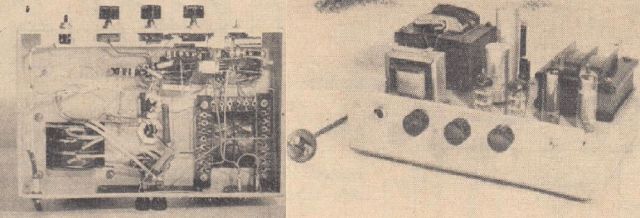
The amplifier described here is perfect as a final power amplifier for playing music from records or tapes in the apartment. It is also suitable for broadcasting dance music in medium-sized halls and clubs.
Construction is easy; it can be performed by any radioamateur with basic theoretical and practical knowledge.
Output stage.
Due to the need to obtain a power equal to at least 10VA with very low nonlinear distortions, I decided to use the output stage amplifier in a push-pull configuration with negative feedback. This is called "ultralinear" system. The feedback voltage in this system is obtained from taps, or from separate windings on the output transformer. By changing the ratio of the alternating voltage of the screen grid to the anode alternating voltage, we change the working conditions of the end tubes. With this ratio equal to one, the tubes work as triodes, because the shielding grids are connected with the anodes, while with the ratio equal to zero, they act as pentodes (Fig. 1).

Fig. 1. "Ultralinear" system.
For the ratios with intermediate values, the circuit has a number of advantages over push-pull circuits, both with triodes and pentodes, and above all, less nonlinear distortions at large and small signals, at the cost of low power loss. Moreover, such feedback significantly reduces the internal resistance of the system.
For EL34 tubes, the 20% tap is the most advantageous (Usz / Ua = 0.2, of course, from the power supply side).
The "ultralinear" circuit with EL84 tubes gives about twice less nonlinear distortions compared to the conventional push-pull circuit with 10% lower power. The "ultralinear" circuit requires a special design of the output transformer.
Output transformer.
Both halves of the anode windings of the transformer should be placed symmetrically by dividing the window into two sections, each for one half of the anode winding. The unbalance has a significant impact on the phase shifts and amplitude differences between the anode current and the screen voltage, so that even harmonics of higher frequencies may not reduce each other.
Fig. 2 shows a diagram of the windings of such a transformer, and Fig. 3 shows the arrangement of the windings.
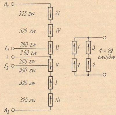
Fig. 2. Diagram of the windings of the output transformer.
Primary windings: 0.18mm copper wire in enamel.
Secondary windings: 0.75mm copper wire in enamel.
Portable universal amplifier
- Details
- Category: Radioamator
- Hits: 8471
Portable universal amplifier.
Radioamator, Rok X, wrzesień 1960, Nr 9 (Radioamateur, Year X, September 1960, No.)
This description concerns the model awarded with the consolation prize in the Great Radio Amateur Model Contest.

From the editorial office:
The amplifier described below is an example of a well-thought-out design for a specific purpose. A simple but full-fledged system, proper use of power thanks to the use of efficient domestic speakers, good adaptability to portability, cheap and effective finish - these are the main features of the device. We can recommend the construction of this device to anyone who wants to have a good portable amplifier for playing recordings from discs, enhancing solo performances and increasing the acoustic power of the receiver when using dance music..
The AMPLIFIER was designed and made for a stage singer producing with an electric guitar. On this assumption, the device should meet the following conditions:
- small dimensions and weight,
- high quality playback,
- high (10W) output power,
- easy to carry and easy to use.
It would be very difficult to meet the above conditions to the full extent, therefore a compromise solution was necessarily applied in the model made. First of all, a system with a mains transformer was adopted (Fig. 1), although in the universal version the weight of the apparatus would be absolutely lower.

Fig. 1. Schematic diagram of the amplifier.
Nevertheless, it was found necessary to galvanically separate the amplifier, microphone and guitar circuits from the network. In contrast, the reduction in dimensions and weight was achieved by a different route. The output power of the amplifier was limited to 5W, filling its final stage with a single EL84 pentode. The reduced output power, in turn, was used as rationally as possible, feeding two lightweight speaker sets with relatively high efficiency.
New types of tubes for push-pull and stereo amplifiers
- Details
- Category: Radioamator i Krótkofalowiec
- Hits: 9458
New types of tubes for push-pull and stereo amplifiers.
Radioamator i Krótkofalowiec, Rok XI, Marzec 1961, Nr 3
Among the many new types of receiver tubes that have recently been introduced to the market by Western European manufacturers, the ELL80 and PLL80 dual speaker pentodes deserve special attention. The idea of placing two tube systems in one bulb has been known since the birth of the now obsolete ECL11 tube, which at the time was a kind of revelation; it was followed by further, more modern types, such as ECL82 ... 86 and their equivalents in the U and P series. Placing two end pentodes in one balloon is, however, something completely new, resulting from the current needs of the electronics industry, in particular from the needs of modern stereo technology.
The final stages of the stereo amplifiers were initially filled with the standard ECC83 + 2xEL84 set, consisting of a total of three tubes. The use of ECL82 tubes made it possible to reduce the number of tubes to two, and - with the same number of stages - had an impact on the cost of the device. However, equipping the same circuit with the ECC83 - ELL80 set is more rational at the same cost, as it allows for a favorable and transparent assembly, allowing you to easily avoid undesirable microphonics, various types of couplings, etc. As you know, two stages with a very strong overall amplification (in the case of an ECL tube) is quite critical and requires careful elaboration of both electrical and mechanical systems in terms of the stability of the system. The popular ECL11 tube was particularly capricious in this respect.
 Fig. 1. Schematic diagram of the 2 x 3W amplifier with ECC83 and ELL80 tubes and its technical parameters.
Fig. 2. Schematic diagram of the 2 x 2.6W amplifier with ECC83 and PLL80 tubes and its technical parameters.
.
Fig. 3. Schematic diagram of the push-pull amplifier with ECC83 and ELL80 tubes and its technical parameters.
Read more: New types of tubes for push-pull and stereo amplifiers
Page 5 of 10
Select your language
")
")
")
")
")